Acoustic medical sensor for ultrasound imaging

a technology of ultrasound imaging and acoustic sensors, which is applied in the direction of catheters, coupling device connections, applications, etc., can solve the problems of large bulky acoustic sensors, difficult to manipulate, and difficult to image the correct tissue plane, and achieve the effect of increasing mobility

Inactive Publication Date: 2005-05-05
SONIVATE MEDICAL
View PDF52 Cites 22 Cited by
  • Summary
  • Abstract
  • Description
  • Claims
  • Application Information

AI Technical Summary

Benefits of technology

[0023] In yet a further embodiment of the invention a sensor is mounted at the end of a tube that is worn over a finger. The tube includes a first portion that covers the first joint of the finger and is rigid. The sensor is disposed within the rigid first portion of the tube. The tube also comprises a second flexible portion, coupled to the first rigid portion. The second portion provides a secure interference fit with the finger, yet allows joints of the finger to freely bend, thereby providing increased mobility over a rigid tube.

Problems solved by technology

Acoustic sensors have tended to be large bulky and difficult to manipulate.
A bulky sensor may make it difficult to maneuver and hence difficult to image the correct tissue plane.
Making a sensor smaller however may lead to difficulty in trying to manipulate, maneuver and position the sensor and may be difficult to apply sufficient pressure, in order to achieve a proper acoustic coupling.
Although large sensors are convenient for applying pressure, they tend to be inconvenient for producing small fine movements.
Such a cable may also impart a torque to the sensor, as it drags behind, making precise manipulation difficult.
Additionally gripping large sensor with enough pressure to hold them steady may produce hand strain.
Another difficulty with sensors is that they may be inconvenient to use.
Additionally there is a need for sensors that are readily available for use by medical professionals, but are easily made unobtrusive when not in use.
Sensors, because of their electronic components and other reasons, may not be sterilizable by all sterilization techniques.

Method used


Image

  • Acoustic medical sensor for ultrasound imaging
  • Acoustic medical sensor for ultrasound imaging
  • Acoustic medical sensor for ultrasound imaging

Examples


Embodiment Construction

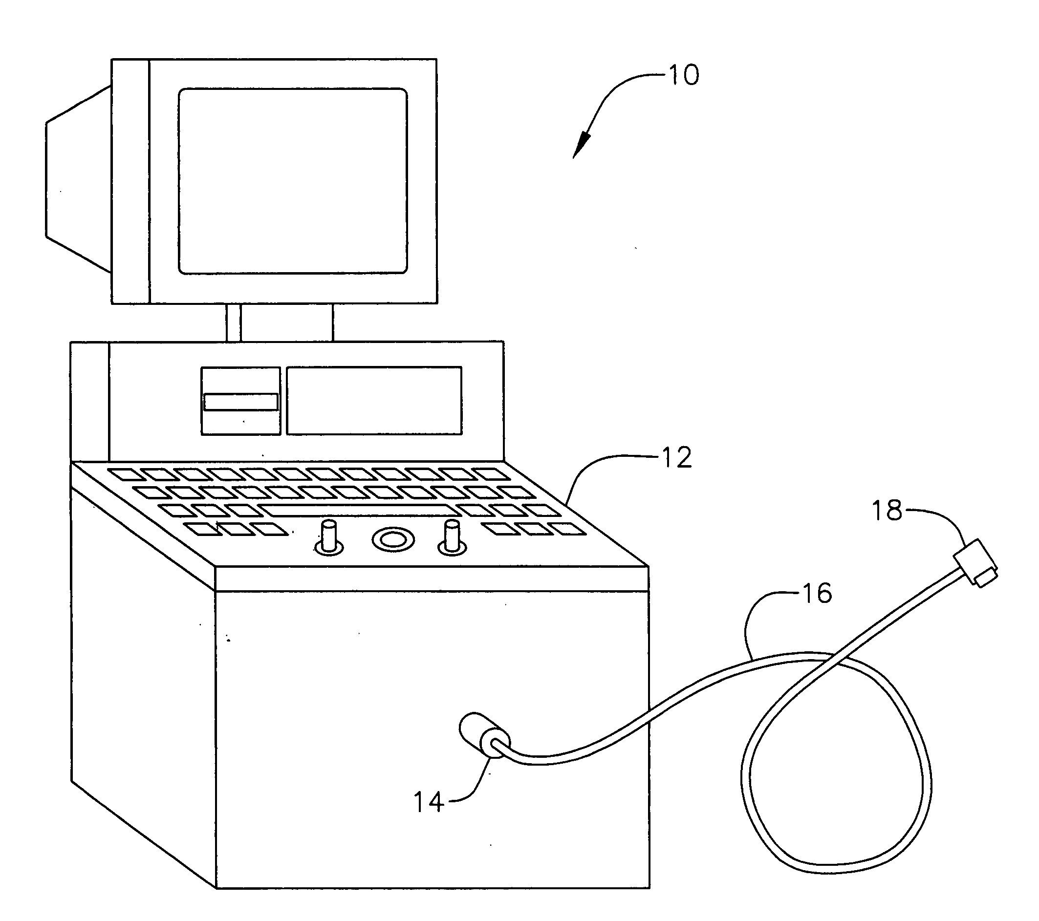
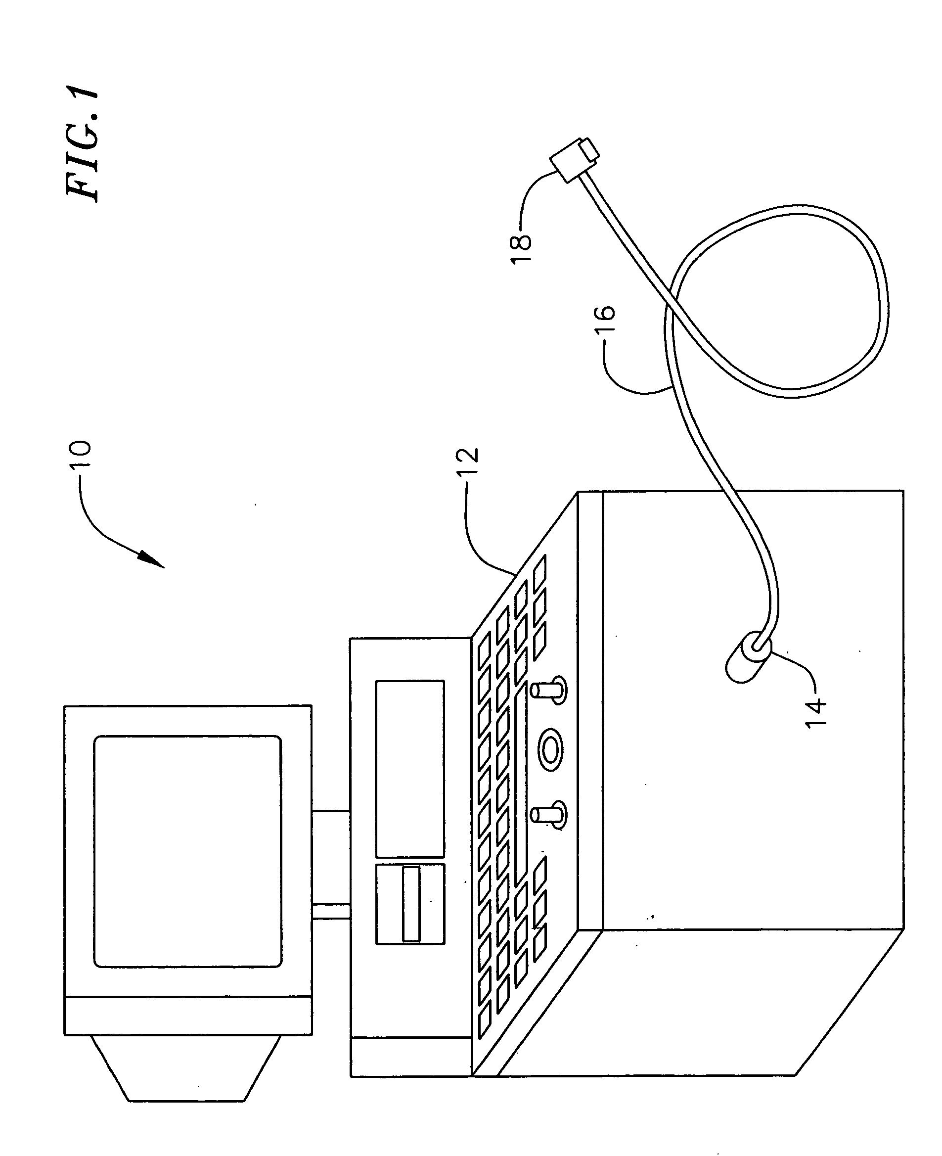
[0055]FIG. 1 is a system diagram of a medical ultrasound system 10 in an exemplary embodiment of the present invention. The medical ultrasound system 10 includes an ultrasound platform 12, which provides a user (e.g., a medical technician) with capabilities to generate, process and display ultrasound images using a probe (also referred to as a probe head or an autoclavable probe) 18. The probe 18 includes a sensor assembly (e.g., a transducer assembly) for taking ultrasound images. For example, the probe 18 may be a sterilizable finger mounted probe, and may include an array of ultrasound sensors for ultrasound imaging.

[0056] The probe 18 is coupled to the platform 12 via a cable 16 and a connector assembly 14. The cable 16 should be a multi-wire cable that can carry multiple signals at the same time. The connector assembly 14 includes a sterilizable connector, which may be a large pin count, low insertion force, steam autoclavable connector suitable for medical ultrasound applicat...


PUM


Abstract

A finger mounted acoustic sensor. Various embodiments of the finger mounted acoustic sensors include sensors mounted within a casing designed to fit between fingers. The sensor may be rotated with respect to the casing. Other embodiments include mounting tubes for wearing on a finger. Sensors are embedded in the tube and on the rings such that they are easily positioned using technician's fingers. Other embodiments include rings for mounting sensors on and for steadying the sensors. The hand and finger mounted sensors may be used to provide necessary pressure to the sensor and yet provide a sensor that may be manipulated using hand and finger motion. In other embodiments sensors having a local disconnect are disclosed. Such disconnects may be attached to the clothing of a medical professional, attached via a wrist or armband or the like. Various sensor packages may be accompanied by the use of a flat or flex cable to minimize the torque necessary to manipulate the sensor. Such sensors can be used with a ultrasound platform for generating, processing and displaying ultrasound images.

Description

CROSS-REFERENCE TO RELATED APPLICATION(S) [0001] This application is a continuation-in-part of U.S. patent application Ser. No. 10 / 724,382 entitled “Immersible Ultrasound Probe and Cable,” filed Nov. 26, 2003, which claims priority to and the benefit of U.S. Provisional Patent Application No. 60 / 429,614 entitled “Steam Autoclavable Ultrasound Probe Connector,” filed Nov. 27, 2002, the entire contents of both of which are incorporated by reference herein.FIELD OF THE INVENTION [0002] The present invention is generally directed to medical imaging sensors and more particularly to hand held acoustic sensors that are used to provide physiological data to electronic medical systems. Such hand held acoustic sensors may be sterilized through immersion in a disinfecting liquid and / or steam autoclaving. BACKGROUND [0003] Acoustic sensors, hereinafter “acoustic sensor”, “sensor” or “sensor array”, are commonly ultrasonic sensors and are widely used for diagnosis and medical testing, imaging in...

Claims


Application Information

Patent Timeline
Patent Type & Authority Applications(United States)
IPC IPC(8): A61B5/02A61B8/00H01R13/24H01R13/52H01R13/533
CPCA61B5/6806A61B5/6826A61B5/6838A61B8/00H01R2201/12A61B2562/187H01R13/2414H01R13/5224H01R13/533A61B8/4209A61B8/4227A61B8/4422A61B8/4455
Inventor DUDIK, EVAN M.SCHUTZ, RONBECK, WILLIAM A. JR.REINISCH, DANADAANE, LAURENCE A.CORBETT, SCOTT S. IIIHOYT, JOSHUA K.PARK, ERICCOOKE, DOUG
Owner SONIVATE MEDICAL
Why Eureka
Try Eureka