Simplified hybrid-secondary uncluttered machine and method

a hybrid-secondary, uncluttered technology, applied in the direction of magnetic circuit rotating parts, magnetic circuit shape/form/construction, windings, etc., can solve the problems of high maintenance cost of motors with slip rings and brushes, high cost of adjustable speed drives fed by adjustable-frequency inverters, and discourage many potential users

Inactive Publication Date: 2005-05-12
UT BATTELLE LLC
View PDF9 Cites 10 Cited by
  • Summary
  • Abstract
  • Description
  • Claims
  • Application Information

AI Technical Summary

Benefits of technology

[0011] This invention provides a simplified form of the hybrid-secondary uncluttered machine in which there is only a stator and a slip energy rotor. The invention eliminates the main rotor and the auxiliary rotor with windings which were present and electrically connected in the prior art. The stator and slip energy rotor are now magnetically coupled and a slip energy source is provided by peripheral transformer coils in which slip current is induced through the magnetic coupling through a rotor without windings.
[0014] This invention further simplifies and improves the earlier machine. It eliminates two large rotating cores and their windings from the earlier machine. It provides higher efficiency due to less copper loss resulting from the elimination of the rotor windings. It can operate at any speed that including synchronous speed. It is smaller in size per unit of power than prior uncluttered machines and can be manufactured at lower cost.

Problems solved by technology

The existing extended rotor cage technology has a drawback in that the both rotational and slip energy are transferred in a cluttered approach to energy transfer.
However, maintenance of a motor with slip rings and brushes is expensive.
The high cost of adjustable speed drives fed by an adjustable-frequency inverter discourages many potential users.

Method used


Image

  • Simplified hybrid-secondary uncluttered machine and method
  • Simplified hybrid-secondary uncluttered machine and method
  • Simplified hybrid-secondary uncluttered machine and method

Examples


Embodiment Construction

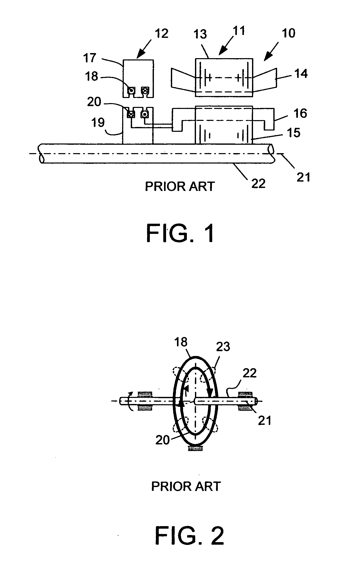
[0032]FIG. 1 illustrates an assembly 10 of an induction motor 11 of the prior art that includes an uncluttered transformer 12 for providing a hybrid secondary. A stator core 13 of the motor 11 is wound with a polyphase winding 14. A rotor core 15 of the motor is wound with a two-phase winding 16. One or more conductors of cast aluminum can also be used on the rotor 15. To the left is a two-phase uncluttered rotating transformer 12. The stator 17 and stator coils 18 of this transformer do not connect to the stator winding 14 of the motor or to the rotor 19 of the transformer 12, but instead are magnetically coupled to the rotor of the transformer. The stator and the rotor of the transformer have coils that are peripherally disposed around the axis of rotation for the motor and the transformer. The electrical connection of the machine rotor to the transformer rotor allows only the slip energy to be present in the rotor of the transformer, and this slip energy is coupled to the stator ...


PUM


Abstract

An electric machine (40, 40′) has a stator (43) and a rotor (46) and a primary air gap (48) has secondary coils (47c, 47d) separated from the rotor (46) by a secondary air gap (49) so as to induce a slip current in the secondary coils (47c, 47d). The rotor (46, 76) has magnetic brushes (A, B, C, D) or wires (80) which couple flux in through the rotor (46) to the secondary coils (47c, 47d) without inducing a current in the rotor (46) and without coupling a stator rotational energy component to the secondary coils (47c, 47d). The machine can be operated as a motor or a generator in multi-phase or single-phase embodiments. A method of providing a slip energy controller is also disclosed.

Description

STATEMENT REGARDING FEDERALLY SPONSORED RESEARCH [0001] This invention was made with Government support under Contract No. DE-AC05-00OR22725 awarded to UT-Battelle, LLC, by the U.S. Department of Energy. The Government has certain rights in this invention.TECHNICAL FIELD [0002] The field of the invention is brushless machines, including both ac and dc machines, including both motors and generators, and including induction machines, permanent magnet (PM) machines and switched reluctance machines. DESCRIPTION OF THE BACKGROUND ART [0003] A brushless doubly-fed induction motor (BDFIM) has two sets of stator windings for two p-poles and two q-poles. The rotor winding has a nested cage with 2(p+q) poles. It produces a motor control with a relatively narrow range of speed control. The existing extended rotor cage technology has a drawback in that the both rotational and slip energy are transferred in a cluttered approach to energy transfer. [0004] An induction machine may be viewed as a t...

Claims


Application Information

Patent Timeline
Patent Type & Authority Applications(United States)
IPC IPC(8): H02K16/04H02K17/42H02K19/24
CPCH02K16/04
Inventor HSU, JOHN S.
Owner UT BATTELLE LLC
Why Eureka
Try Eureka