
Optical transmitter for use in high-density wavelength division multiplexing (WDM) optical transmission system

a wavelength division multiplexing and optical transmission system technology, applied in the field of optical transmitters, can solve the problems of deteriorating reception sensitivity compared to a return-to-zero on-off key (rz-ook) signal, affecting the performance of the transmitter, so as to improve the performance of the high-density wavelength division multiplexing (wdm) long-distance optical transmission system. , the effect of high reception

Inactive Publication Date: 2005-05-12
SAMSUNG ELECTRONICS CO LTD
View PDF5 Cites 13 Cited by
  • Summary
  • Abstract
  • Description
  • Claims
  • Application Information

AI Technical Summary

Benefits of technology

[0011] The present invention has been made in view of the above problems, and it is an object of the present invention to provide an optical transmitter for generating an RZ-AMI signal which contains not only high reception sensitivity but also a narrow spectrum bandwidth, such that it can improve performance of a high-density Wavelength Division Multiplexing (WDM) long-distance optical transmission system.

Problems solved by technology

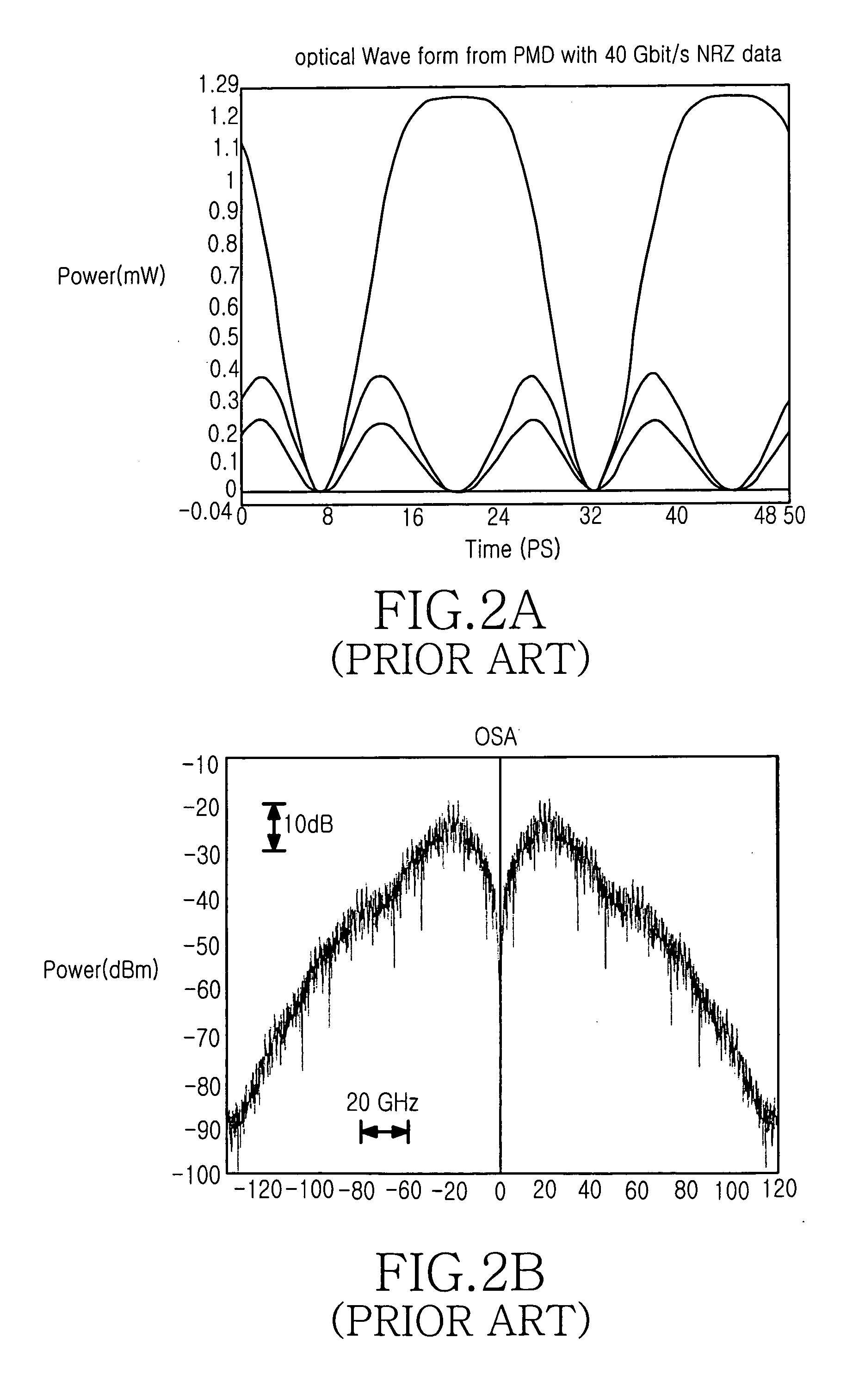
Referring to the output signal's eye diagrams shown in FIG. 2A, the conventional RZ-AMI optical transmitter positions a sinusoidal signal at a frequency double the data transfer rate at a specific level value of 0, resulting in deteriorated reception sensitivity compared to a return-to-zero on-off key (RZ-OOK) signal.
In other words, the RZ-AMI signal generated from the conventional optical transmitter is very sensitive to noise, resulting in deterioration of a maximum transfer distance.
Disadvantageously, transmitter performance varies with the pattern length of the received electric signal.
Furthermore, the conventional RZ-AMI optical transmitter temporally uses an RZ modulation scheme as can be seen from the output signal's spectrums shown in FIG. 2B, and requires a wide bandwidth, such that it cannot acquire high spectrum efficiency (e.g., 0.6 bit / s / Hz).

Method used


Image

  • Optical transmitter for use in high-density wavelength division multiplexing (WDM) optical transmission system
  • Optical transmitter for use in high-density wavelength division multiplexing (WDM) optical transmission system
  • Optical transmitter for use in high-density wavelength division multiplexing (WDM) optical transmission system

Examples


Embodiment Construction

[0021] Preferred embodiments of the present invention are described in detail below with reference to the annexed drawings. In the following description, details of known functions and configurations incorporated herein are omitted for clarity of presentation.

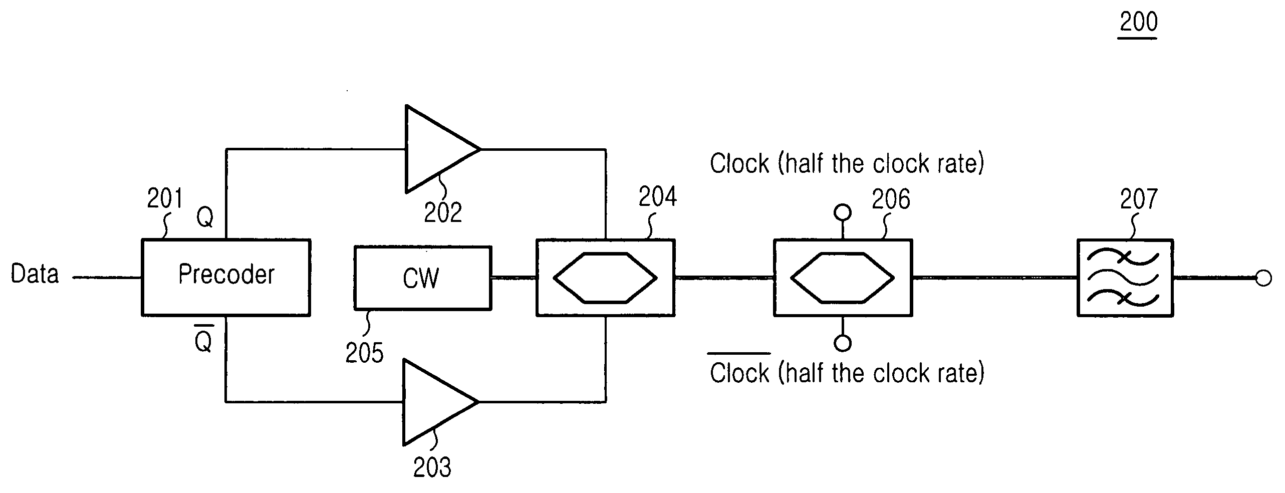
[0022]FIG. 3 is a block diagram showing, by way of illustrative and non-limitative example, the RZ-AMI optical transmitter 200 in accordance with a preferred embodiment of the present invention. The transmitter 200 includes a precoder 201, modulation drive amplifiers 202, 203, a CW laser 205, first and second MZ MODs 204, 206, and an optical filter 207.

[0023] The precoder 201 codes an input binary data signal, and can be implemented with a 1-bit delay and an XOR (exclusive-OR) logic gate.

[0024] The modulation drive amplifiers 202, 203 amplify the coded binary data such that they can operate the modulator.

[0025] The CW laser 205 outputs an optical carrier signal as a light source.

[0026] The first and second MZ MODs 204, 206...


PUM


Abstract

An optical transmitter for use in high-density WDM (Wavelength Division Multiplexing) optical transmission system generates an RZ-AMI (Return to Zero—Alternate Mark Inversion) signal which contains not only high reception sensitivity suitable for a high-density WDM optical transmission system, but also a narrow spectrum bandwidth. The transmitter includes a precoder for coding an input binary-data electric signal, a modulation drive amplifier for amplifying the coded signal, a light source for generating an optical carrier signal, a first optical modulator for modulating a phase of the optical carrier signal upon receiving the amplified signal from the amplifier, a second optical modulator for modulating an output signal of the first optical modulator into an RZ (Return to Zero) signal, and an optical filter for filtering an output signal of the second optical modulator to tailor the output signal for a predetermined bandwidth.

Description

CLAIM OF PRIORITY [0001] This application claims priority to an application entitled “OPTICAL TRANSMITTER FOR USE IN HIGH-DENSITY WAVELENGTH DIVISION MULTIPLEXING (WDM) OPTICAL TRANSMISSION SYSTEM,” filed in the Korean Intellectual Property Office on Nov. 12, 2003 and assigned Serial No. 2003-79866, the contents of which are hereby incorporated herein by reference. BACKGROUND OF THE INVENTION [0002] 1. Field of the Invention [0003] The present invention relates to an optical transmitter, and more particularly to an optical transmitter for generating an RZ-AMI (Return to Zero—Alternate Mark Inversion) signal which contains not only high reception sensitivity suitable for a high-density Wavelength Division Multiplexing (WDM) optical transmission system, but also a narrow spectrum bandwidth. [0004] 2. Description of the Related Art [0005] Typically, an Alternate Mark Inversion (AMI) modulation scheme loads information on the intensity of an optical signal, and at the same time inverts ...

Claims


Application Information

Patent Timeline
IPC IPC(8): H04B10/516G02F1/035H04B10/524H04B10/556H04B10/588H04B10/61H04J14/00H04J14/02
CPCH04B10/505H04B10/5051H04J14/02H04B10/5167H04B10/5055H04B10/50H04B10/2581
Inventor KIM, HOONOH, YUN-JEHWANG, SEONG-TAEK
Owner SAMSUNG ELECTRONICS CO LTD
Learn More