Charged-particle multi-beam exposure apparatus

a multi-beam, charge-particle technology, applied in the field of charge-particle multi-beam exposure apparatus, can solve the problem that the reliability of sources scales with the number of sources, and achieves the effect of facilitating the generation of complex patterns, facilitating shielding out unwanted magnetic and electromagnetic fields, and enhancing beam autonomy

Active Publication Date: 2005-05-19
IMS NANOFABTION
View PDF11 Cites 86 Cited by
  • Summary
  • Abstract
  • Description
  • Claims
  • Application Information

AI Technical Summary

Benefits of technology

[0034] In order to enhance the autonomy of the beams and facilitate generation of complex patterns a PD means may be provided for each particle beam, where the PD means has a pattern field in which the apertures are located, said pattern field having a length of at least 500 times the size of the apertures. Likewise, for each particle beam a pattern definition means may be provided with at least 20000 apertures whose transparency to the particle beam can be electronically controlled between switched on and off states.
[0035] An advantageous layout of the device re

Problems solved by technology

However, it should be appreciated that the apparatus disclosed in the U.S. Pat. No. 6,768,125 is not, as such, suitable for use in a multi-beam device; rather an modifi

Method used


Image

  • Charged-particle multi-beam exposure apparatus
  • Charged-particle multi-beam exposure apparatus
  • Charged-particle multi-beam exposure apparatus

Examples


Embodiment Construction

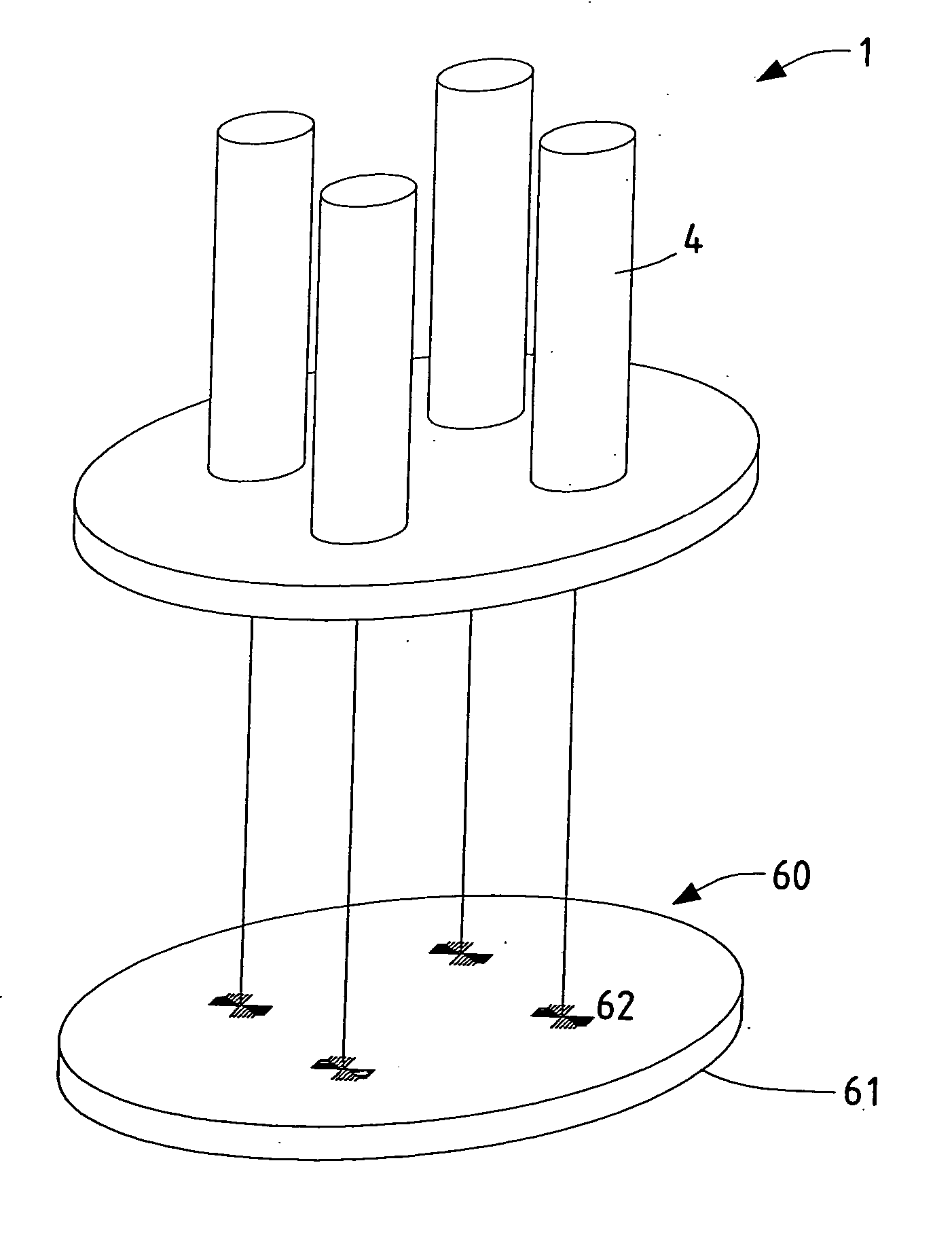
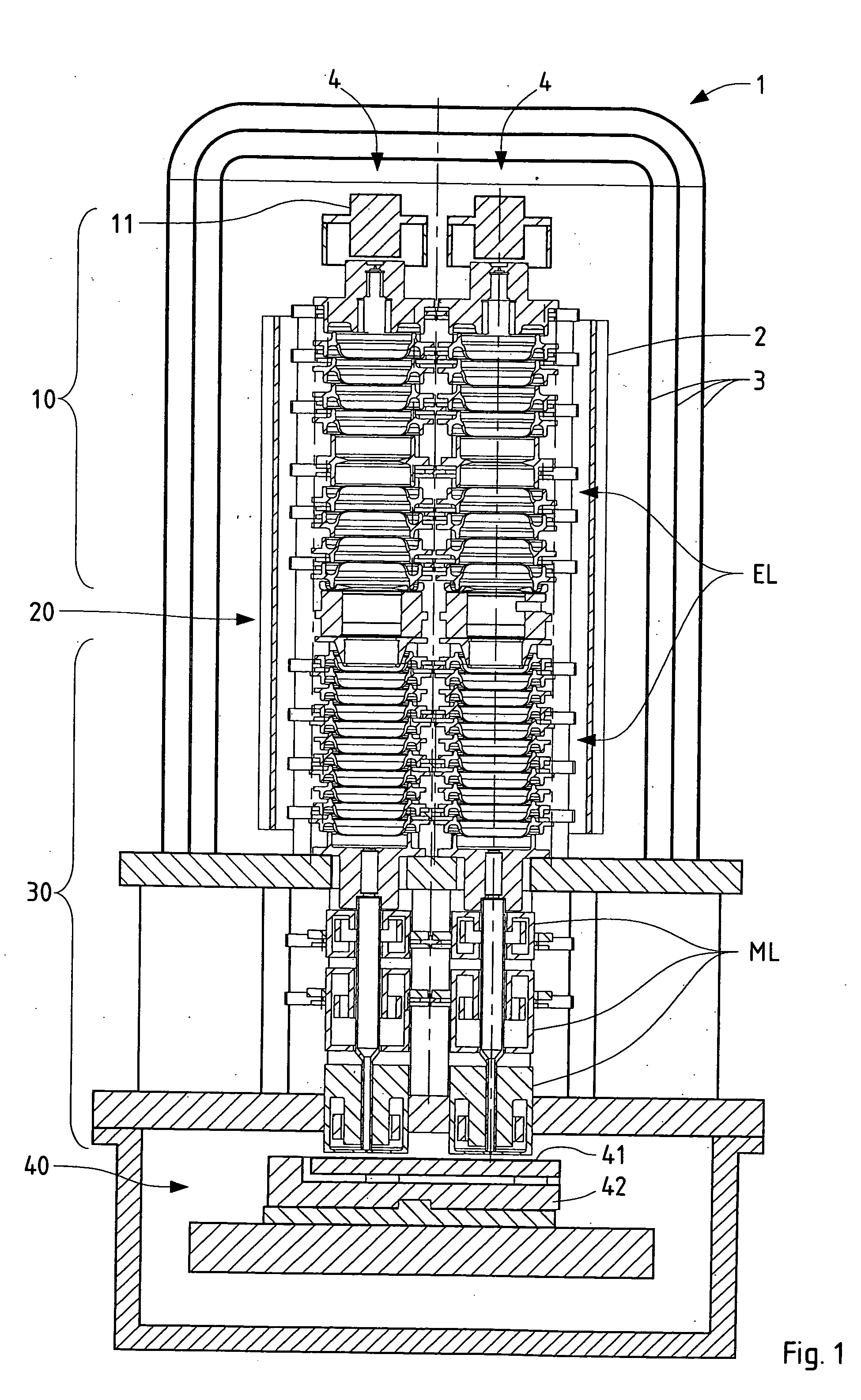
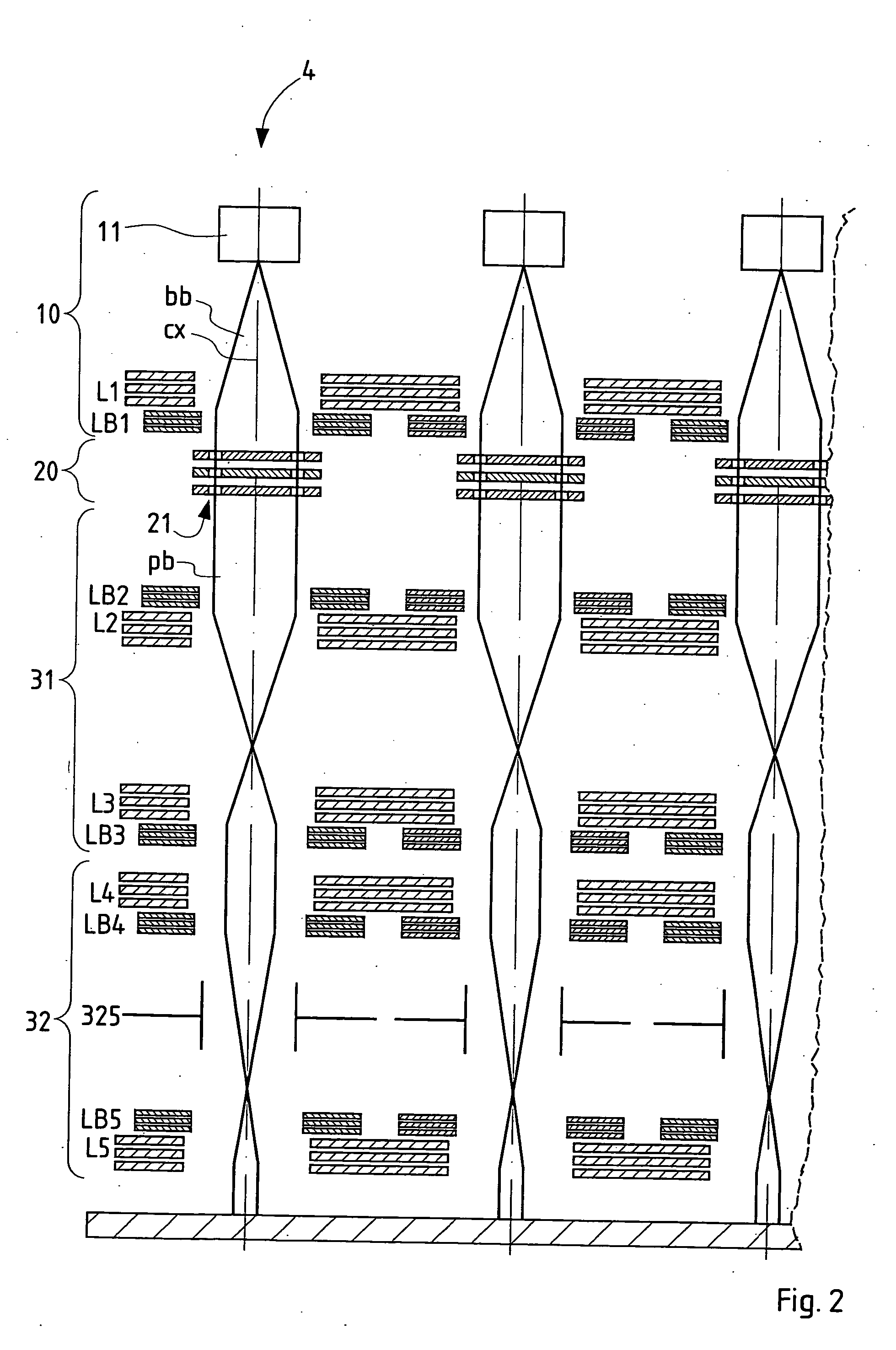
[0049] A preferred embodiment of the invention is shown in FIG. 1. Four columns are combined in a 2×2 arrangement of a multicolumn apparatus 1 for exposing a wafer held in the target chamber representing the bottom of the apparatus. The longitudinal section of FIG. 1 runs through two neighboring columns 4. FIG. 2 shows a schematic longitudinal-section view illustrating the basic elements of the device of FIG. 1. (For the sake of clarity, the columns are shown in FIG. 2 as if they were arranged in a single plane.)

[0050] Major improvements of the embodiment over the prior art are, for example, that it offers a large redundancy in the pattern generation process on the one side, and an avoidance of alignment problems between different columns on the other side. It represents a novel implementation of multi-column and multi-beam (per column) approach, based on the above-mentioned U.S. Pat. No. 6,768,125. Furthermore, it allows to partially reduce or even circumvent technical risk issues...


PUM


Abstract

A charged-particle multi-beam exposure apparatus (1) for exposure of a target (41) uses a plurality of beams of electrically charged particles, which propagate along parallel beam paths towards the target (41). For each particle beam an illumination system (10), a pattern definition means (20) and a projection optics system (30) are provided. The illuminating system (10) and/or the projection optics system (30) comprise particle-optical lenses having lens elements (L1, L2, L3, L4, L5) common to more than one particle beam. The pattern definition means (20) defines a multitude of beamlets in the respective particle beam, forming its shape into a desired pattern which is projected onto the target (41), by allowing it to pass only through a plurality of apertures defining the shape of beamlets permeating said apertures, and further comprises a blanking means to switch off the passage of selected beamlets from the respective paths of the beamlets.

Description

FIELD OF THE INVENTION AND DESCRIPTION OF PRIOR ART [0001] The invention relates to a charged-particle multi-beam exposure apparatus used for forming a pattern on a surface of a target, such as a semiconductor substrate, by means of a set of beams of energetic electrically charged particles. More in detail, the invention relates to a charged-particle multi-beam exposure apparatus for exposure of a target with a plurality of beams of electrically charged particles, said particle beams propagating along parallel beam paths towards the target; for each of said particle beams an illumination system, a shaping means and a projection optics system are provided, with the illumination system being adapted to produce the beam and form it into a substantially telecentric beam illuminating the shaping means, the shaping means being adapted to form the shape of the illuminating beam into a desired pattern, and the projection optics system being adapted to project an image of the beam shape defi...

Claims


Application Information

Patent Timeline
IPC IPC(8): G03F7/20H01J37/317H01L21/027
CPCB82Y10/00H01J37/3177H01J37/3174B82Y40/00H01J3/06H01J37/08
Inventor STENGL, GERHARDPLATZGUMMER, ELMARLOSCHNER, HANS
Owner IMS NANOFABTION
Why Eureka
Try Eureka