

Fuel cell and separator for cooling used therein
a fuel cell and separator technology, applied in the field of protonexchange membrane fuel cells, can solve the problems of increased electric resistance and voltage drop of the separator, the apex of the corrugated sheet is difficult to be flattened, and the electroconductive sheet gasket is not applicable to the metallic separator having passages provided, etc., to achieve the effect of reducing contact resistance, reducing electric resistance and reducing contact resistan
- Summary
- Abstract
- Description
- Claims
- Application Information
AI Technical Summary
Benefits of technology
Problems solved by technology
Method used
Image

Examples
example 1
(Example 1)
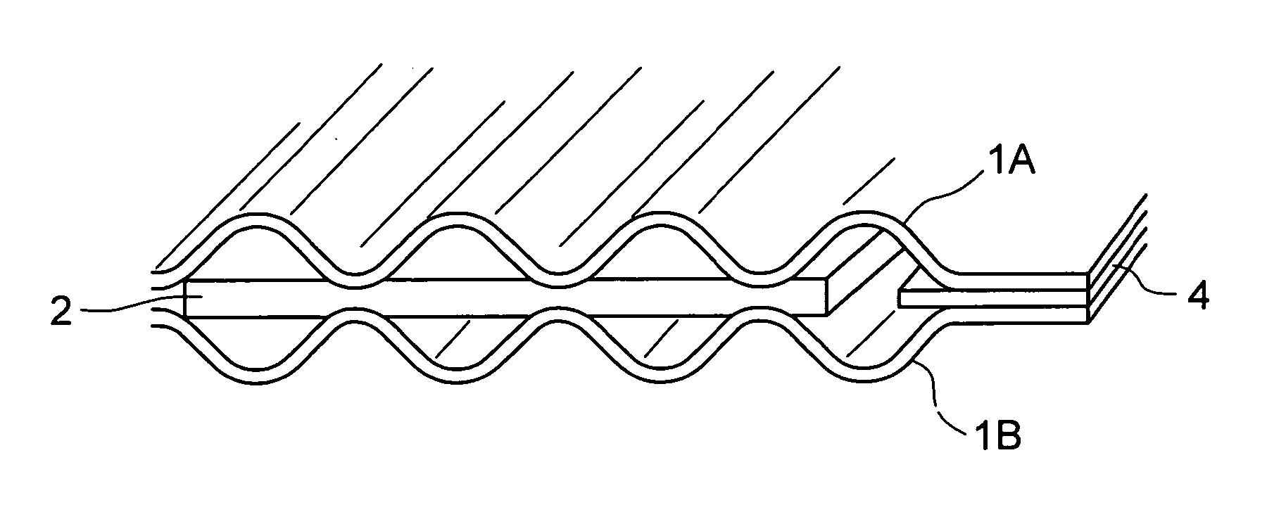
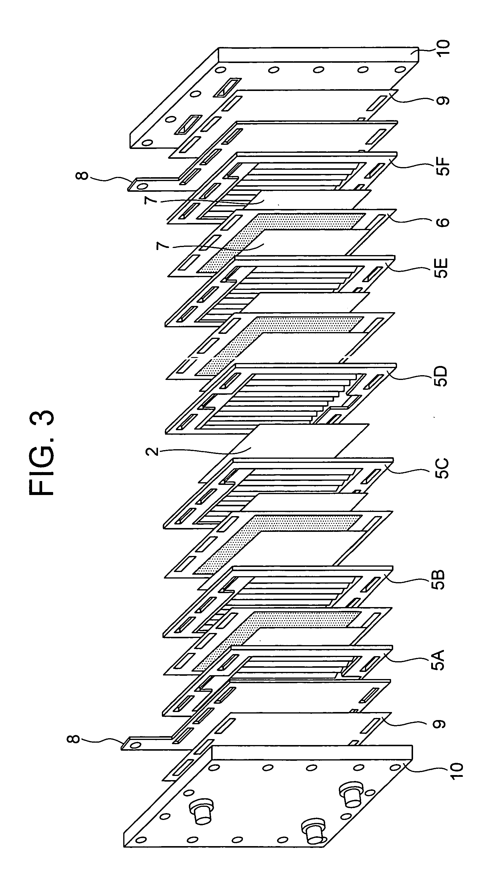
[0031] EXAMPLE 1 of the present invention is described. FIG. 3 is a developed view illustrating the fuel cell of the present invention. FIG. 4 illustrates one of the gasket-provided separator assembly structures 5A to 5F, shown in FIG. 3. First, the gasket-provided separator assembly structure 5 is described. It has a structure with the gasket 4 put on the separator 1 as the substrate. The separator 1, 160 mm by 120 mm, was made of 0.2 mm thick thin stainless steel (Type 304) (or AISI 304) overhang-stamped to have linear passage grooves at the center, where flat section 103 was provided around passage grooves as tabs for sealing. The passage groove section was 100 mm by 100 mm, and each groove was 2 mm wide (including width of the apexes) and 0.5 mm deep. The gasket 4 was put on the flat section 103, to direct cooling water (or reaction gas in the case of the power-generating cell) from the manifolds 101 provided in the separator towards the passage grooves 102. Therefore...
example 2
(Example 2)
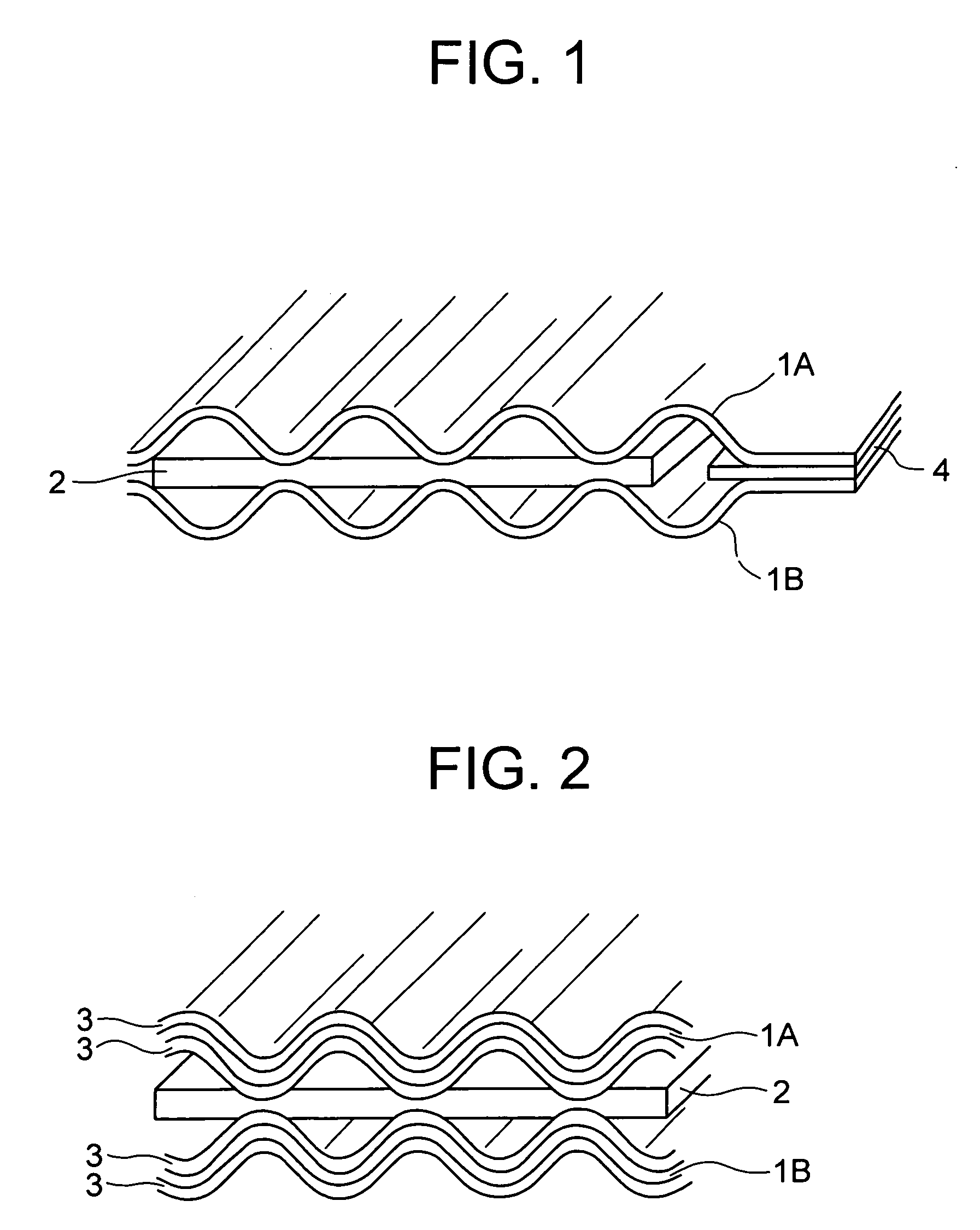
[0037] The intermediate 2 described in EXAMPLE 1 was a flat plate. It may be replaced by the slit-structured intermediate 2A, which is the intermediate 2 whose portion not contacting with the separator 1 is removed. FIG. 5 is a plan illustrating the slit-structured intermediate 2A, and FIG. 6 the intermediate 2A assembled in a cooling cell. The intermediate 2A was machined by an adequate means, e.g., punching, to have a plurality of the slits 201A by removing the portions not contacting with the separator 1, as shown in FIG. 5. It was held by a pair of the gasket-provided separators 5 in such a way that the rib apex in the gasket-provided separator assembly 5 comes into contact with the corresponding lattice 202A in the intermediate 2.
[0038] Use of the intermediate 2A can increase cooling water passage cross-section, thereby reducing pressure loss resulting from flow of water, with the result that the fuel cell has enhanced efficiency. The intermediate 2 described in EXA...
example 3
(Example 3)
[0039] In EXAMPLE 3, power generation by the fuel cell prepared in EXAMPLE 1 is described, where a load was applied to the fuel cell by an electronic loading device. An optional load can be applied to the fuel cell by connecting the electronic loading device to the 2 current-collecting plates in the fuel cell to pass a given current between them. The fuel gas and oxidizing agent supplied to the fuel cell were pure hydrogen and air. They were passed through a humidifier beforehand to have a given dew point. Temperature of the cooling water was controlled at the inlet port, at which the fuel cell operated at a constant temperature.
[0040] The power was generated under the following conditions, hydrogen utilization: 80%, oxygen utilization: 40%, fuel gas dew point: 60° C., oxidizing agent dew point: 50° C. and cell temperature: 70° C., where a load was applied to the cell after temperature and flow rate became steady. The power was generated at a constant rate for 24 hours a...
PUM
 Abstract
Description
Claims
Application Information