
Internal combustion engine with exhaust-gas turbocharger and secondary air injection

a technology of exhaust gas and turbocharger, which is applied in the direction of machines/engines, electrical control, mechanical equipment, etc., can solve the problems of high cost of air mass sensors, for example based on hot-film strain gauges, and sensitive to soiling

Inactive Publication Date: 2005-05-26
DAIMLER AG
View PDF10 Cites 38 Cited by
  • Summary
  • Abstract
  • Description
  • Claims
  • Application Information

AI Technical Summary

Benefits of technology

[0007] This has the advantage that there is no need for complex temperature-measuring methods as have been employed hitherto. Rotational speed measurement can be carried out contactlessly and with absolutely no wear in particular using inductive rotational speed sensors. Moreover, these inductive rotational speed sensors can be miniaturized and produced at extremely low cost.
[0009] In the preferred embodiment, the exhaust-gas turbocharger of the internal combustion engine which simultaneously compresses the charge air can be used to compress the secondary air. If a separate compressor is used to compress the secondary air, the two compression processes for the supercharging of the internal combustion engine and for the compression of the secondary air can be separated by virtue of the two flow paths for the charge air and for the secondary air beginning upstream of the compressor of the exhaust-gas turbocharger. The solution according to the invention also results in an advantageous method for monitoring the secondary air injection. This is because the change in rotational speed of the exhaust-gas turbocharger as a result of the secondary air injection is used to determine and control the quantity of secondary air delivered. Moreover, by monitoring the rotational speed of the exhaust-gas turbocharger it is possible to diagnose the secondary air injection by comparing the measured rotational speed of the exhaust-gas turbocharger with an expected, desired rotational speed corresponding to the operating point of the internal combustion engine and concluding that the secondary air injection is defective if there is a deviation from the expected, desired rotational speed.

Problems solved by technology

Air mass sensors, for example based on hot-film strain gauges, are expensive and sensitive to soiling.

Method used


Image

  • Internal combustion engine with exhaust-gas turbocharger and secondary air injection
  • Internal combustion engine with exhaust-gas turbocharger and secondary air injection
  • Internal combustion engine with exhaust-gas turbocharger and secondary air injection

Examples


Embodiment Construction

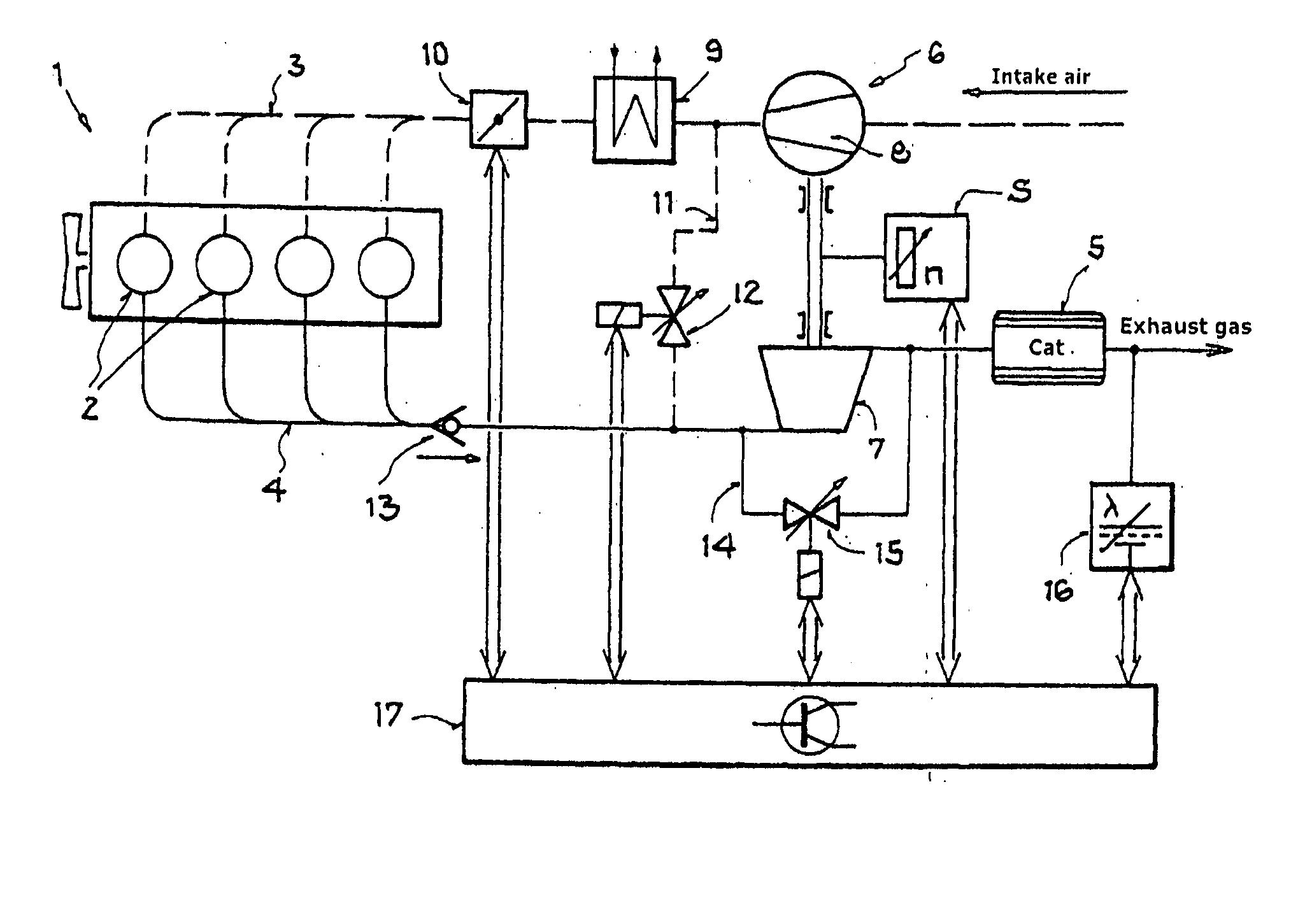
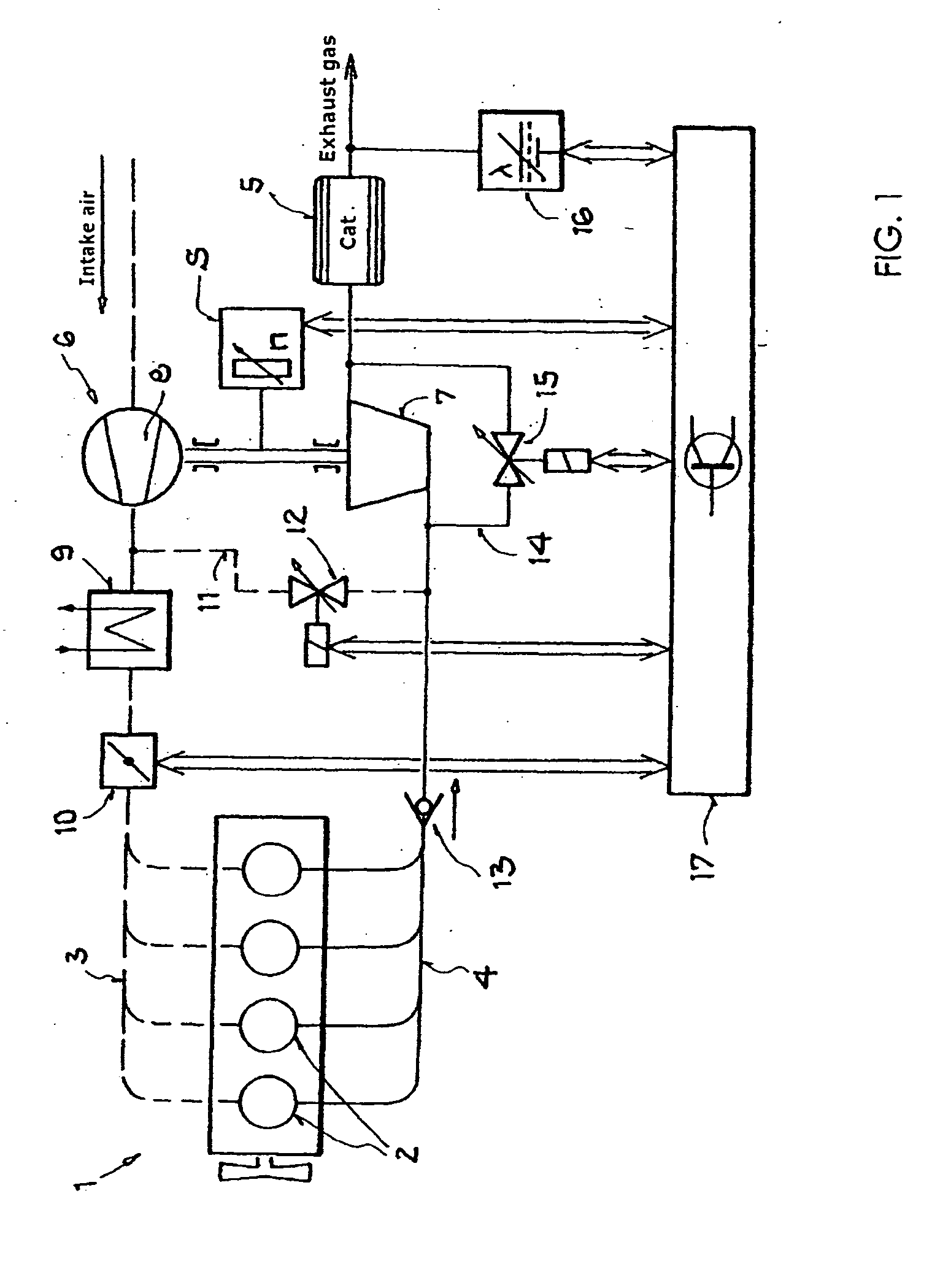
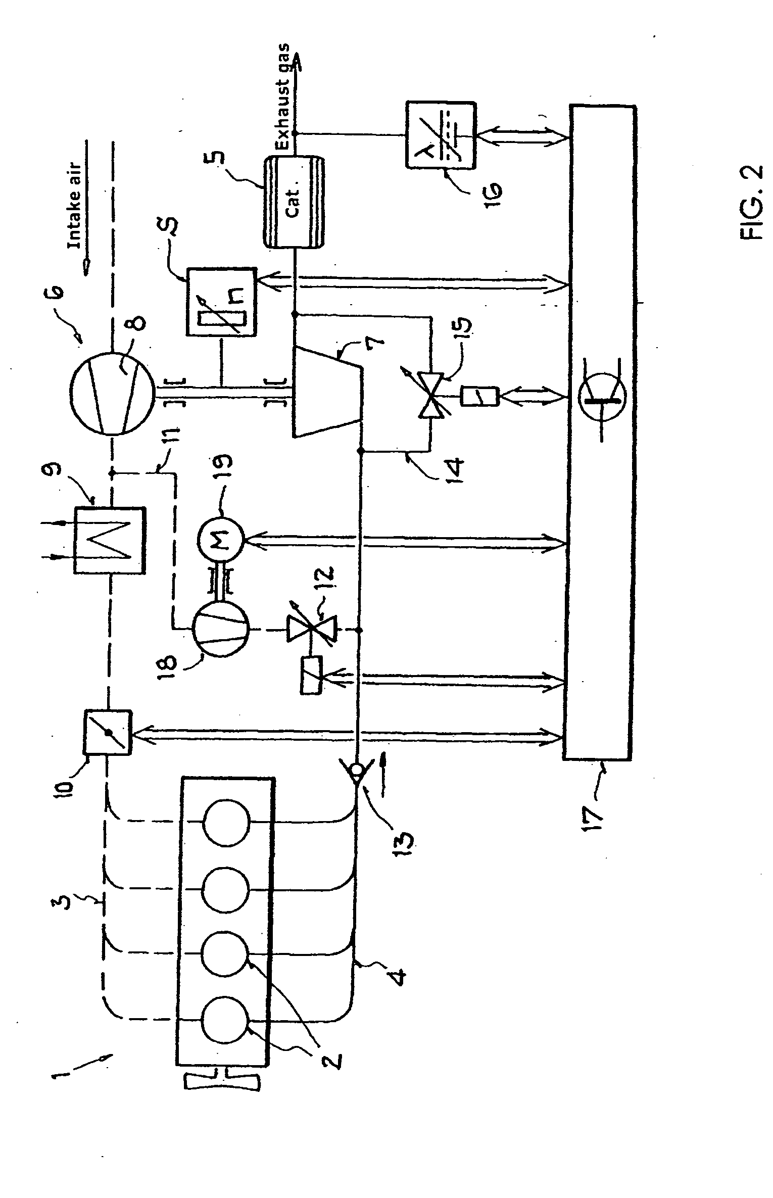
[0015]FIG. 1 shows an internal combustion engine 1 having a plurality of combustion cylinders 2, which is supplied with charge air via an intake section 3, indicated by dashed lines, and fuel is added to the charge air with internal or external mixture formation. This ignitable mixture is ignited in the combustion cylinders 2, and the combustion products are discharged from the combustion cylinders via the exhaust system 4, which is illustrated by solid lines, and fed to a catalytic converter 5 for catalytic aftertreatment. An exhaust-gas turbocharger 6 has its turbine 7 in the flow path of the exhaust system and its compressor 8 in the flow path of the intake air. The compressed intake air can optionally be cooled using a charge-air cooler 9. For charge-air control, a throttle valve 10 is provided downstream of the charge-air compressor 8 and the charge-air cooler 9. A secondary-air line 11 branches off from the intake section downstream of the charge-air compressor 8 and leads, vi...


PUM


Abstract

The invention relates to an internal combustion engine which has charge-air supercharging by means of an exhaust-gas turbocharger and secondary air injection, the flow path of which is selected in such a way that the quantity of secondary air injected has an influence on the rotational speed of the turbocharger. By monitoring the rotational speed of the turbocharger, an increase in the rotational speed caused by the secondary air injection is determined, and the quantity of secondary air injected is worked out from the increase in rotational speed. This has the advantage that there is no need for complex temperature-measuring methods as have hitherto been employed. Rotational speed measurement can be carried out contactlessly and with absolutely no wear in particular by means of inductive rotational-speed sensors. Moreover, these inductive rotational-speed sensors can be miniaturized and produced at extremely low cost.

Description

CROSS REFERENCE TO RELATED APPLICATION [0001] This application claims the priority of German Patent Application No. 103 48 131.1, filed on Oct. 16, 2003, the subject matter of which, in its entirety, is incorporated herein by reference. FIELD OF THE INVENTION [0002] The invention relates to an internal combustion engine with secondary air injection into the exhaust system of the internal combustion engine for aftertreatment of the combustion products in the exhaust-gas stream. Furthermore, the invention relates to a method for monitoring the secondary air injection and to the possibility of diagnosing the secondary air injection. BACKGROUND OF THE INVENTION [0003] En route to what is now the customary catalytic aftertreatment of the exhaust gases from an internal combustion engine, it was initially attempted to reduce exhaust emissions by thermal afterburning. Thermal afterburning allows the unburnt constituents still present in the exhaust gas to be afterburnt by a certain residenc...

Claims


Application Information

Patent Timeline
IPC IPC(8): F02D45/00F01N3/20F01N3/22F01N3/30F01N3/34F02B37/00F02B37/013F02B37/04F02B37/16F02B37/18F02D23/00
CPCF01N3/20F01N3/22F01N3/30F01N2550/14F02B37/00Y02T10/20F02B37/04F02B37/16F02B37/18Y02T10/144F02B37/013F02B37/168Y02T10/12
Inventor BUSCH, MICHAEL-RAINER
Owner DAIMLER AG
Learn More