
Combination of imaging member and functional base for new utility

a functional base and imaging member technology, applied in the field of imaging display materials, can solve the problems of reducing manufacturing efficiency or image quality, reducing image quality, and reducing image quality, so as to improve optical, mechanical and texture features, and reduce manufacturing and printing complexity

Inactive Publication Date: 2005-05-26
BOURDELAIS ROBERT P +2
View PDF14 Cites 7 Cited by
  • Summary
  • Abstract
  • Description
  • Claims
  • Application Information

AI Technical Summary

Benefits of technology

[0016] It is another object to provide display materials having improved optical, mechanical and texture features.
[0017] It is a further object to reduce the manufacturing and printing complexity of new support materials.

Problems solved by technology

Cost is also an important consideration as display materials tend to be expensive compared with alternative display material technology mainly lithographic images on paper.
For display materials, traditional color paper is undesirable as it suffers from a lack of durability for the handling, photoprocessing and display of large format images.
The addition of the white pigments into the polyester sheet causes several manufacturing problems which can either reduce manufacturing efficiency or reduce image quality.
The addition of white pigment to the polyester base causes manufacturing problems such as die lines and pigment agglomeration which reduce the efficiency at which photographic display material can be manufactured.
The TiO2 in the polyester gives the reflective display materials an undesirable opalescent appearance.
The TiO2 pigmented polyester also is expensive because the TiO2 must be dispersed into the entire thickness, typically from 100 to 180 micrometers.
This also gives the polyester support a slight yellow tint which is undesirable for a photographic display material.
The number of differentiated display materials tend to be limited as there are several complexities in the manufacturing and the image creation step which need to be overcome.
Examples of manufacturing and image creation complexities which have limited the variety of support materials include web conveyance in manufacturing, imaging layer adhesion, photographic reactivity, conveyance in printers, and unwanted interaction with processing chemistry.

Method used


Image

  • Combination of imaging member and functional base for new utility
  • Combination of imaging member and functional base for new utility
  • Combination of imaging member and functional base for new utility

Examples


example 1

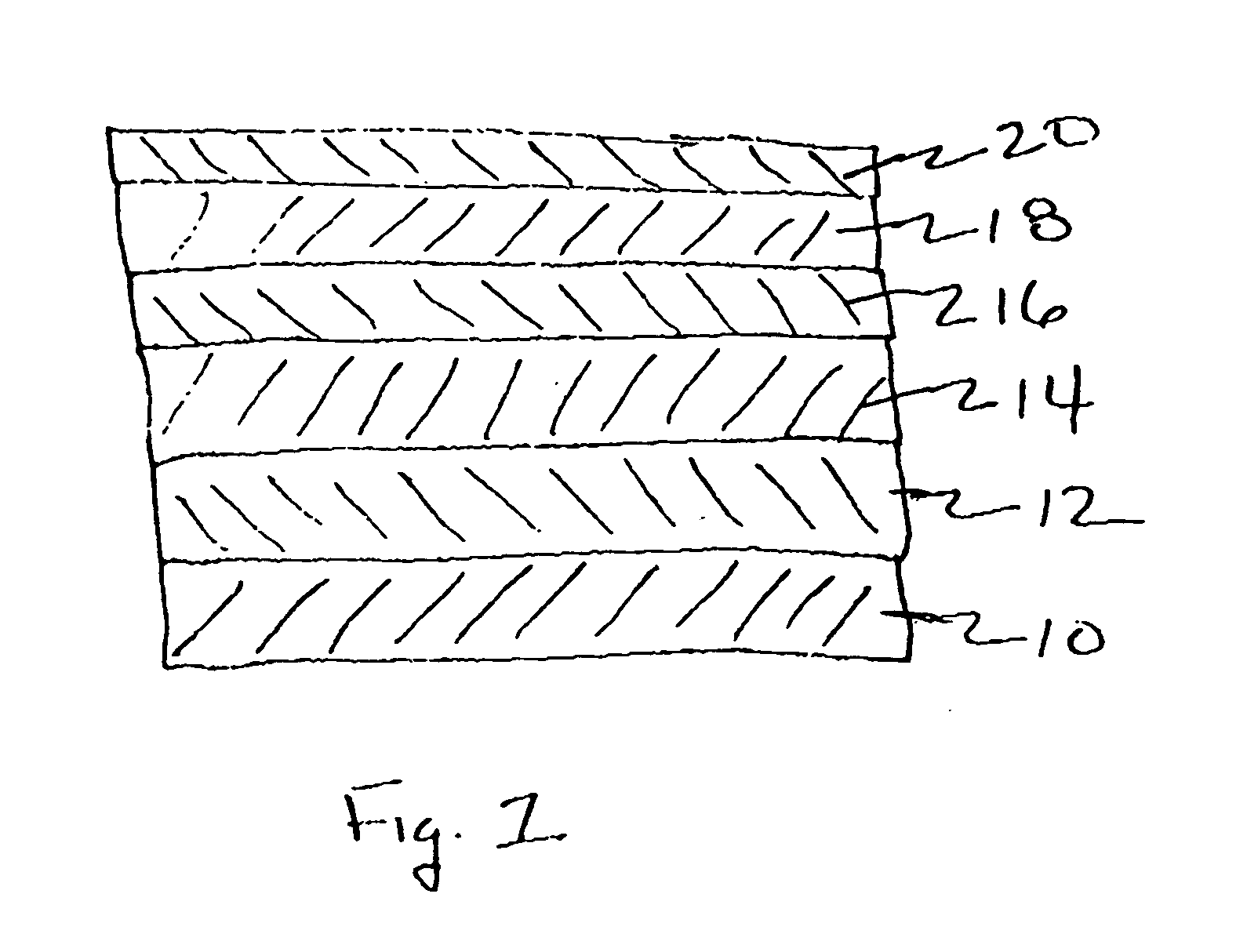
[0111] In this example a silver halide pressure sensitive imaging member was created by applying a light sensitive silver halide imaging layers to an opaque polymer sheet. The opaque polymer sheet consisted of a flexible white biaxially oriented polypropylene face stock backside coated with a pressure sensitive adhesive that was adhesive laminated to a paper carrier sheet. The light sensitive silver halide imaging layers were a yellow, magenta, and cyan coupler system capable of accurate reproduction of flesh tone. After processing the imaging member, the photographic label was coated with an environmental protection layer to protect the delicate silver halide imaging layers from environmental solvents. The image member was then pressure sensitive laminated to a variety of functional bases to demonstrate a new image utility.

Biaxially Oriented Polyolefin Polymer Sheet:

[0112] A composite sheet polyolefin sheet (150 μm thick) (d=0.68 g / cc) consisting of a microvoided and oriented po...


PUM

PropertyMeasurementUnit
thicknessaaaaaaaaaa
thicknessaaaaaaaaaa
thickaaaaaaaaaa

Abstract

The invention relates to an article comprising an image member comprising a polymer sheet having an image adhered thereto permanently adhered to a functional base wherein said image member and said functional base interact to create a new image utility and wherein said polymer sheet has a thickness of less than 250 micrometers.

Description

FIELD OF THE INVENTION [0001] This invention relates to imaging display materials. In a preferred form it relates to base and imaging layers for commercial display. BACKGROUND OF THE INVENTION [0002] It is known in the art that photographic display materials are utilized for advertising as well as decorative displays of photographic images. Since these display materials are used in advertising, the image quality of the display material is critical in expressing the quality message of the product or service being advertised. Further, a photographic display image needs to be high impact, as it attempts to draw consumer attention to the display material and the desired message being conveyed. Typical applications for display material include product and service advertising in public places such as airports, buses and sports stadiums, movie posters and fine art photography. The desired attributes of a quality, high impact photographic display material are a slight blue density minimum, ...

Claims


Application Information

Patent Timeline
Patent Type & Authority Applications(United States)
IPC IPC(8): G03C7/00B41M7/00G03C1/795G03C1/805G03C7/20G03C11/14G03G8/00G09F3/02G09F13/04G09F13/22
CPCB41M7/0027G03C11/14Y10T428/24802G09F13/22Y10T428/24479G03G8/00
Inventor BOURDELAIS, ROBERT P.GIARRUSSO, TIMOTHY J.SMITH, PHILIP J.
Owner BOURDELAIS ROBERT P
Learn More