Method for extending the dynamic detection range of assay devices

a dynamic detection and assay technology, applied in the field of dynamic detection range extension of assay devices, can solve the problems of inability to detect the capture of probes by most optical detection techniques, high analyte concentration, and many conventional lateral flow assays encounter significant inaccuracy, so as to achieve the effect of improving the accuracy of detection and compensation signals under actual test conditions

Inactive Publication Date: 2005-05-26
KIMBERLY-CLARK WORLDWIDE INC
View PDF99 Cites 99 Cited by
  • Summary
  • Abstract
  • Description
  • Claims
  • Application Information

AI Technical Summary

Benefits of technology

[0009] The accuracy of the detection and compensation signals under actual test conditions may be further improved using self-calibration techniques. Specifically, the porous membrane is also in communication with calibration probes and comprises a calibration zone within which a third capture reagent is immobilized that is

Problems solved by technology

Despite the benefits achieved from these devices, many conventional lateral flow assays encounter significant inaccuracies when exposed to relatively high analyte concentrations.
For example, assays that rely on optical detection (e.g., fluorescence, reflectance, phosphorescence, etc.) often become inaccurate at high analyte concentrations.
Unfortunately, most optical det

Method used


Image

  • Method for extending the dynamic detection range of assay devices
  • Method for extending the dynamic detection range of assay devices
  • Method for extending the dynamic detection range of assay devices

Examples


example 1

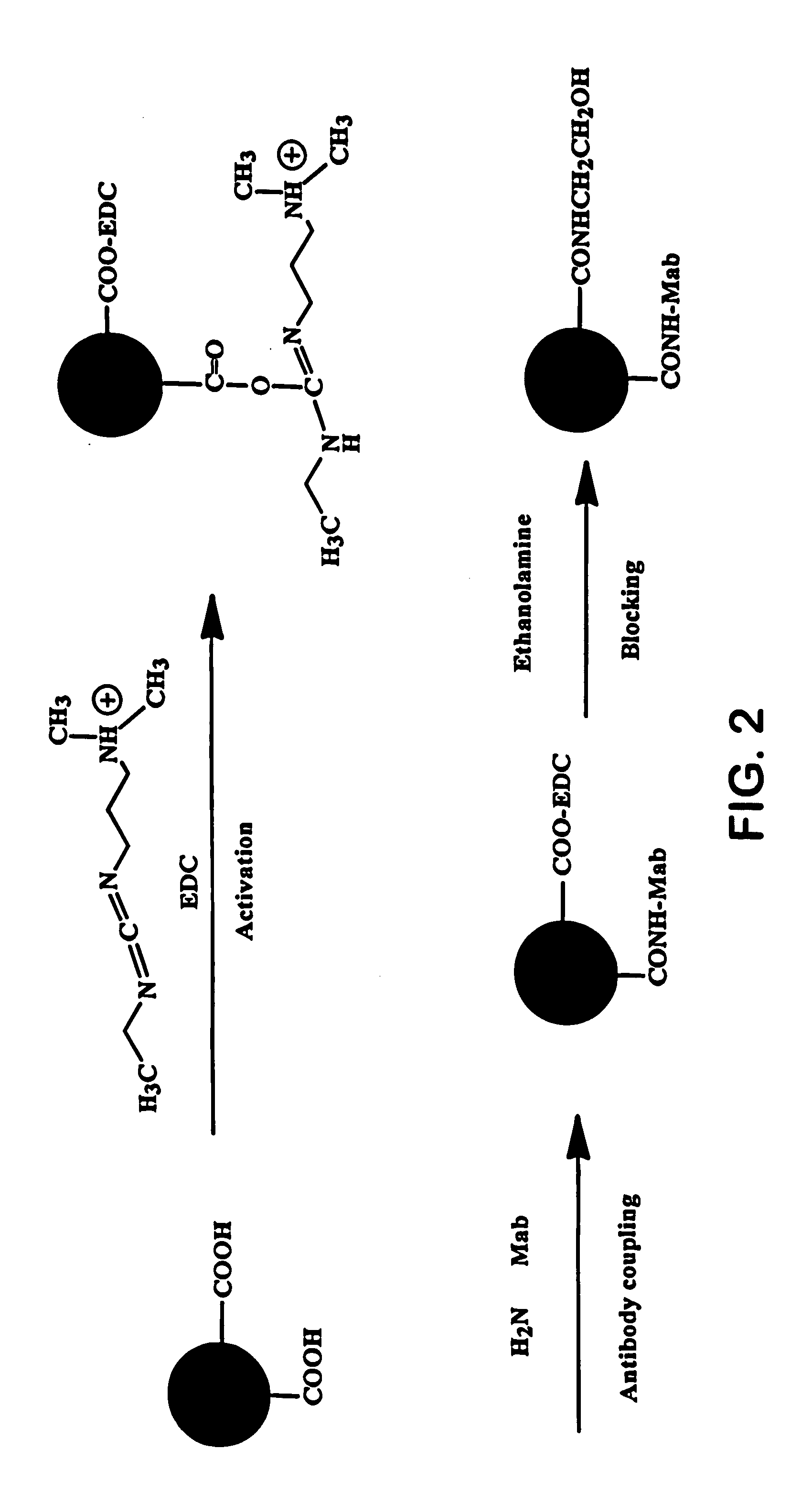
[0064] Conjugated fluorescent detection probes were formed in the following manner. Carboxylated latex particles were encapsulated with europium chelates having a particle size of 0.20 micrometers, a 0.5% solids concentration, and exhibiting fluorescence at an emission wavelength of 615 nanometers when excited at a wavelength of 370 nanometers. The particles were obtained from Molecular Probes, Inc. and designated as “Eu—P.”

[0065] Initially, 500 microliters of the particles were washed once with 1 milliliter of a carbonate buffer and twice with 2-[N-morpholino]ethanesulfonic acid (MES) buffer (pH: 6.1, 20 millimolar) using a centrifuge. The washed particles were re-suspended in 250 microliters of MES. Thereafter, 3 milligrams of carbodiimide (Polysciences, Inc.) was dissolved in 250 microliters of MES and added to the suspended particles. The mixture was allowed to react at room temperature for 30 minutes on a shaker. The activated particles were then washed twice with a borate buff...

example 2

[0066] Conjugated fluorescent calibration probes were formed as described in Example 1, except that CRP Mab1 was replaced with Rabbit anti Goat IgG (Cat #41-RG15 from BiosPacific, Inc. Inc.) or Goat anti Rabbit IgG (Cat #41-GR30 from BiosPacific, Inc. Inc). The conjugated fluorescent calibration probes were designated as “Eu—P 41-RG15” and “Eu—P 41-GR30”, respectively.

example 3

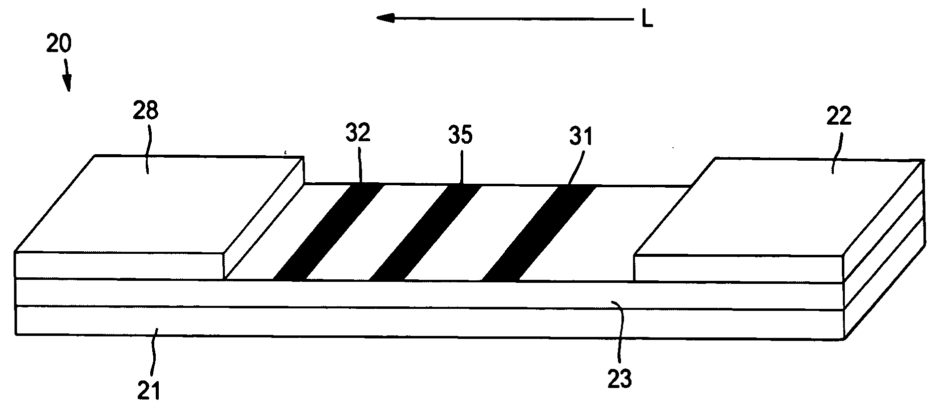
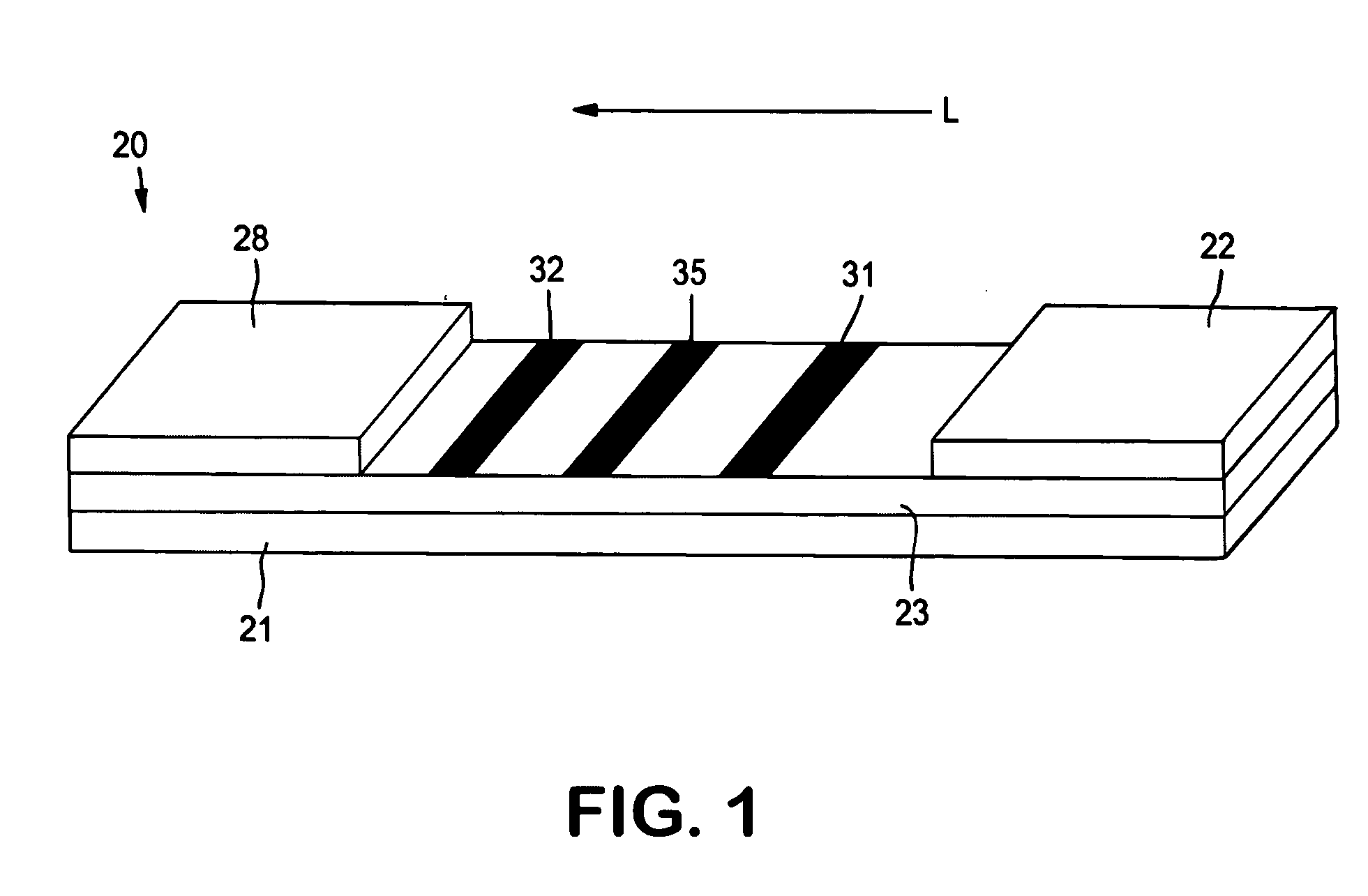
[0067] The ability to form a lateral flow assay device with a detection zone and a compensation zone was demonstrated. A nitrocellulose porous membrane (HF 12002 from Millipore, Inc.) having a length of approximately 30 centimeters was laminated onto supporting cards. Goldline™ (a polylysine solution obtained from British Biocell International) was stripped onto the membrane to form a compensation zone. In addition, monoclonal antibody for C-reactive protein (CRP Mab2) (A#5804, available from BiosPacific, Inc., concentration of 1 milligram per milliliter) was immobilized on the porous membrane to form a detection zone. The membrane samples were then dried for 1 hour at a temperature of 37° C.

[0068] A conjugate pad was prepared as described below. 250 microliters of Eu—P CRP conjugated fluorescent detection particles of Example 1 (concentration of 2.5 milligrams per milliliter in Hepes buffer) was mixed with 375 microliters of Tween 20 (2%, available from Aldrich) and 375 microliter...


PUM

PropertyMeasurementUnit
Concentrationaaaaaaaaaa
Electric chargeaaaaaaaaaa
Ratioaaaaaaaaaa

Abstract

A flow-through assay device for detecting the presence or quantity of an analyte residing in a test sample is provided. The device utilizes a detection zone and compensation zone within which are immobilized capture reagents. The present inventor has discovered that the presence of a compensation zone may enable the detection of an analyte over extended concentration ranges. In particular, the compensation zone facilitates the binding of probes that would otherwise bind within the interior of assay device or that would exhibit “self-quenching.”

Description

BACKGROUND OF THE INVENTION [0001] Various analytical procedures and devices are commonly employed in flow-through assays to determine the presence and / or concentration of analytes that may be present in a test sample. For instance, immunoassays utilize mechanisms of the immune systems, wherein antibodies are produced in response to the presence of antigens that are pathogenic or foreign to the organisms. These antibodies and antigens, i.e., immunoreactants, are capable of binding with one another, thereby causing a highly specific reaction mechanism that may be used to determine the presence or concentration of that particular antigen in a biological sample. [0002] There are several well-known immunoassay methods that use immunoreactants labeled with a detectable component so that the analyte may be detected analytically. For example, “sandwich-type” assays typically involve mixing the test sample with detectable probes, such as dyed latex or a radioisotope, which are conjugated wi...

Claims


Application Information

Patent Timeline
IPC IPC(8): B64D45/00G01N33/543G06F17/00G07C5/08
CPCB64D45/0015B64D2045/0035G01N33/54366G01N33/54393G07C5/085G07C5/0883G08B13/19669G08B13/19634G08B13/19641G08B13/1965G08B13/19656G08B13/19663G07C5/0891B64D45/0053
Inventor SONG, XUEDONG
Owner KIMBERLY-CLARK WORLDWIDE INC
Why Eureka
Try Eureka