Performance measurement system with quantum dots for object identification

a performance measurement and quantum dots technology, applied in the field of performance measurement systems with optical wavelength discrimination and fluorescent markers, can solve the problems of ineffective devices, non-fluorescent paint or ink-based markers and devices in bright sunlight, insufficient optical discrimination of markers, etc., to achieve the effect of increasing fluorescence tim

Active Publication Date: 2005-05-26
ACUSHNET CO
View PDF100 Cites 58 Cited by
  • Summary
  • Abstract
  • Description
  • Claims
  • Application Information

AI Technical Summary

Benefits of technology

[0022] One advantage of using fluorescent markers comprising quantum dots is the increased fluorescence time. In one embodiment, the fluorescence time of the quantum dots is preferably about 200 ns or less. More preferably, the fluorescence time of the quantum dots is about 150 ns or less. In some embodiments, the quantum dots comprise semiconductors. In other embodiments, the quantum dots comprise gold atoms encapsulated in poly-amid amine dendrimers. It is desirable for the emission spectrum of the quantum dots to be varied based on the diameter of the quantum dots.

Problems solved by technology

Retro-reflective markers, however, result in a raised surface when placed on the golf ball and effect flight performance of the golf ball.
In addition, non-fluorescent paint or ink-based markers and devices are ineffective in bright sunlight and do not provide sufficient optical discrimination of markers.
Devices for measuring two sports objects in a single swing are known, however, these systems have drawbacks relating to outdoor functionality, portability, accuracy, and ease of use.

Method used


Image

  • Performance measurement system with quantum dots for object identification
  • Performance measurement system with quantum dots for object identification
  • Performance measurement system with quantum dots for object identification

Examples


Embodiment Construction

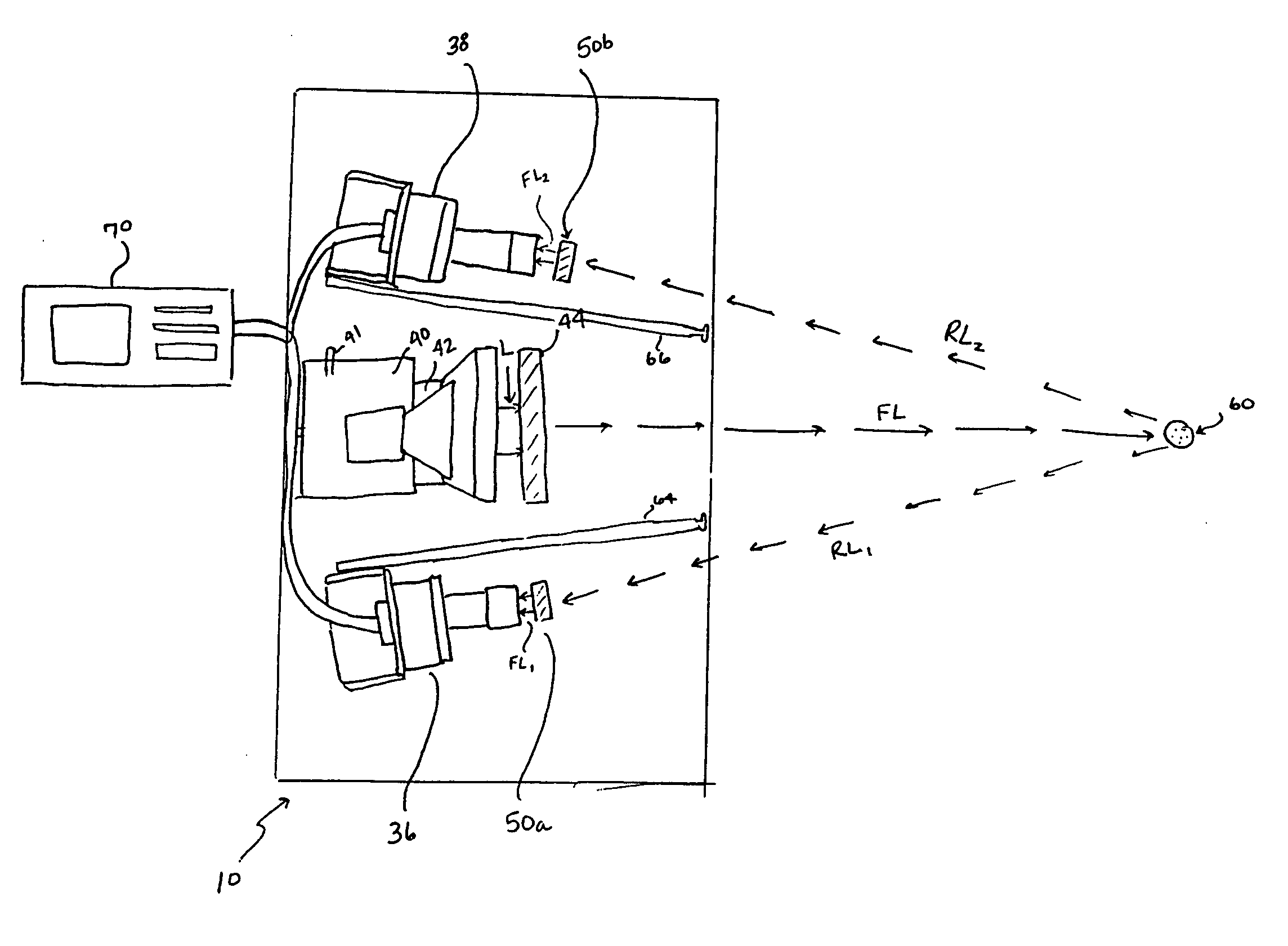
[0041] The present invention is related to a portable and accurate method and apparatus for measuring golf performance. In particular, the kinematic characteristics of an object are measured, such as a golf ball and a golf club, using at least one fluorescent marker, camera, filter, and central processing unit. The camera, lighting system, and markings on the object allow measurements, at discrete time intervals, of an object's position and orientation in a predetermined field-of-view.

[0042] The apparatus includes at least one lighting unit, used to direct light in the direction of the object and filtered through at least one light filter, or otherwise controlled, to allow only selected wavelengths of the light to contact the object, and at least one camera unit, with at least one camera filter, configured to point toward the object. The light illuminates the object to cause the fluorescent markers to reflect light toward the camera. The camera filter allows only a portion of the r...


PUM


Abstract

The present invention is directed to a monitor system that measures flight characteristics of at least one object moving in a predetermined field-of-view using at least one fluorescent marker. In one embodiment, the emission spectra of the fluorescent marker is preferably narrow and substantially symmetric. It may be desirable for the fluorescent marker to be capable of responding to a broad excitation spectra. Preferably, the fluorescent markers comprise quantum dots. The quantum dots may be manufactured in any desired manner, and may comprise semiconductors, gold atoms, and the like.

Description

CROSS-REFERENCE TO RELATED APPLICATIONS [0001] This application is a continuation-in-part application of U.S. application Ser. No. 10 / 002,174 filed on Dec. 5, 2001, now pending, which is incorporated in its entirety by reference herein.FIELD OF THE INVENTION [0002] The present invention relates to a monitor system with optical wavelength discrimination and fluorescent markers comprising quantum dots. More particularly, the present invention relates to a system for monitoring kinematics of golf equipment and a method for use thereof. BACKGROUND OF THE INVENTION [0003] Devices for measuring golf ball flight characteristics and club head swing characteristics are known. For example, the golf ball or golf club head may be marked with at least one contrasting area, used to generate optical images that may be used to determine performance characteristics. Some of these devices use retro-reflective tape or paint markers. Retro-reflective markers, however, result in a raised surface when pl...

Claims


Application Information

Patent Timeline
Patent Type & Authority Applications(United States)
IPC IPC(8): A63B43/00A63B59/00A63B43/06A63B69/00A63B69/36A63B71/06G01B11/00G01P3/36G01P3/38G01P3/40
CPCA63B24/0003G01P3/40A63B24/0021A63B43/008A63B59/0074A63B59/0092A63B69/3614A63B69/3623A63B69/3658A63B71/06A63B71/0622A63B2024/0031A63B2024/0034A63B2024/0043A63B2207/02A63B2220/05A63B2220/13A63B2220/16A63B2220/20A63B2220/24A63B2220/30A63B2220/35A63B2220/40A63B2220/803A63B2220/805A63B2220/806A63B2220/807A63B2220/808A63B2225/20A63B2243/0029G01P3/38A63B24/0006A63B2102/32A63B60/54A63B60/42A63B2225/74
Inventor GOBUSH, WILLIAM
Owner ACUSHNET CO
Why Eureka
Try Eureka