[0012] In light of the situation of the prior arts, the object of the present invention is to provide a power
control unit for electric vehicle which can easily detach the
high voltage cables even if the motor room is deformed, for example, by head-on collision and / or rear-end collision of the vehicle, which is difficult to be deformed, which can makes small, and which can avoid an influence of heat generated by the reactor.
[0014] In such a configuration, the devices for controlling
electric power supply of said electric vehicle are accommodated within the box, while the reactor is supported on a given external wall surface of the box. Specifically, the reactor is provided outside of the box. For this reason, the
radiant heat from the reactor or such is directed towards the outside of the box. The reactor
receiver also serves as enhancing the rigidity. The
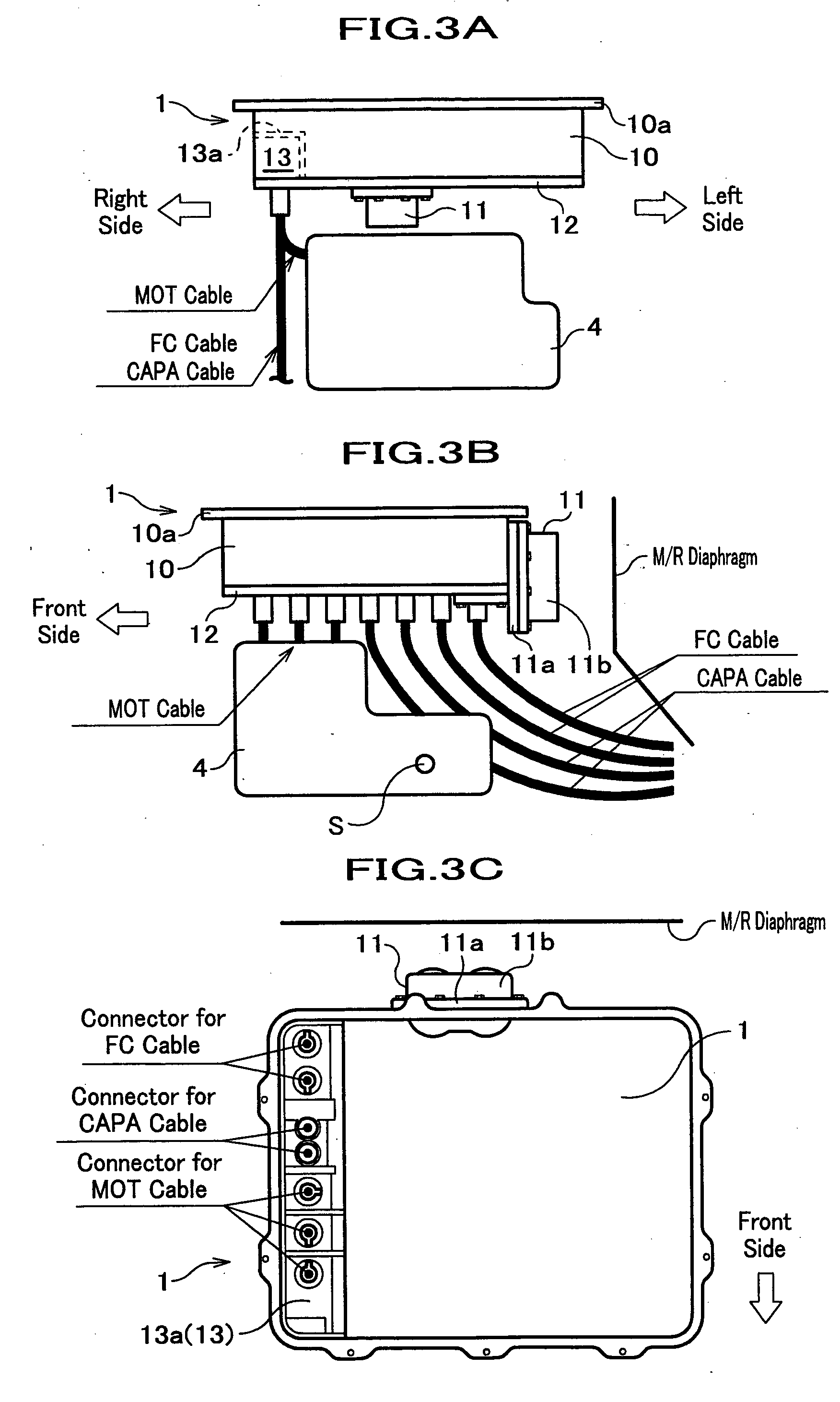
heat sink, which covers the bottom surface of the box, has a function of enhancing the rigidity of the bottom of the box. Since the heat sink and the lower end of the reactor receiver are connected with each other, a force, for example, the force inputted to the reactor receiver, is distributed into the bottom surface of the box having been covered with the heat sink. Also, the beam member for communicating with the cables enhances the side (side wall) of the box. In addition, since the cables are communicated with the side of the box, cables can easily be disposed at the position where the traction motor residing at the lower portion of the heat sink (box) is avoided. In this case, the length of the cable does not become so long. Since the cables are communicated with the side of the box, the length of the box in the longitudinal direction can be shortened.
[0018] In the power
control unit according to this preferred embodiment, in the case where a force is inputted to the longitudinal direction, the possibility of deforming the heat sink is reduced, improving the total rigidity of the box. The wall surface used herein
dose not mean to distinguish the wall, ceiling, and floor from each other.
[0020] In the power control unit according to this preferred embodiment, the portions taken out the
electric cables (
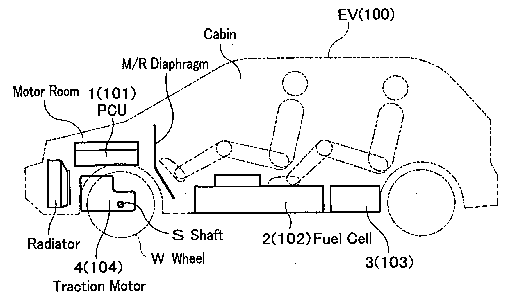
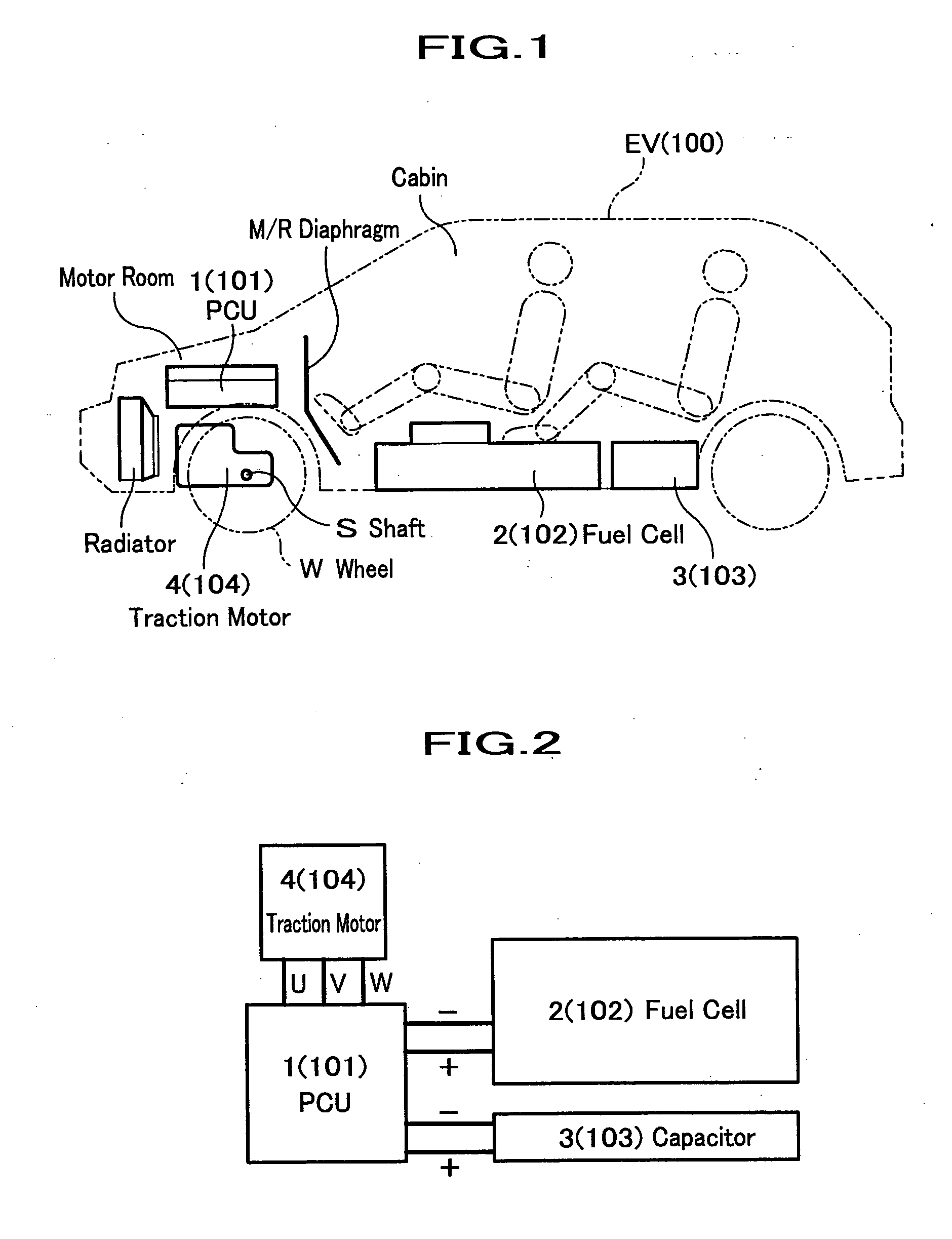
high voltage cables) are side portion of the traction motor. Consequently, even in the case of head-on collision and / or rear-end collision of the vehicle, which are the most frequent case of the collision of vehicle, the geometric arrangement of cables does not make narrow, and sufficient clearance of the cables can be ensured. Accordingly, the motor room can be shortened. This makes it possible to design the vehicle such that the total length of the vehicle body is shortened. In addition, the length of the cabin in the longitudinal direction can be also reduced.
[0022] In the power control unit according to this preferred embodiment, the portions taken out the
electric cables (high
voltage cables) are side portion of the traction motor. Consequently, even in the case of head-on collision and / or rear-end collision of the vehicle, which are the most frequent case of the collision of vehicle, the geometric arrangement of cables does not make narrow, and sufficient clearance of the cables can be ensured. Accordingly, the motor room can be shortened. This makes it possible to design the vehicle such that the total length of the vehicle body is shortened. In addition, the length of the cabin in the longitudinal direction can be also reduced. In addition, the catching the
electric cables into the space between the traction motor and the power supply device can be prevented, because the portions taken out the electric cables (high
voltage cables) are side portion of the traction motor.
[0024] In the power control unit according to this preferred embodiment, the portions taken out the electric cables (high
voltage cables) are side portion of the traction motor. Consequently, even in the case of head-on collision and / or rear-end collision of the vehicle, which are the most frequent case of the collision of vehicle, the geometric arrangement of cables does not make narrow, and sufficient clearance of the cables can be ensured. Accordingly, the motor room can be shortened. This makes it possible to design the vehicle such that the total length of the vehicle body is shortened. In addition, the length of the cabin in the longitudinal direction can be also reduced. In addition, the catching the electric cables into the space between the traction motor and the power supply device can be prevented, because the portions taken out the electric cables (high voltage cables) are side portion of the traction motor.



