Charged-particle beam lithographic system

a lithographic system and charge-particle technology, applied in the direction of beam/ray deflecting arrangement, electron beam welding apparatus, optical radiation measurement, etc., can solve problems such as surface appearance, and achieve the effect of improving writing accuracy

Inactive Publication Date: 2005-06-02
JEOL LTD
View PDF3 Cites 7 Cited by
  • Summary
  • Abstract
  • Description
  • Claims
  • Application Information

AI Technical Summary

Benefits of technology

[0012] In order to solve the foregoing problem with the prior art, it is an object of the present invention to provide a lithographic method offering an improved writing accuracy by correcting variations in the image magnification caused by variations in the strength (excitation) of a lens.
[0016] As described previously, the charged-particle beam lithographic system according to the present invention (A) corrects the size by controlling the shaping deflector according to the strength of the objective lens and (B) corrects the irradiation position on the workpiece by controlling the positioning deflector based on the correction of the size. By performing the correction (A), the size of the pattern written on the workpiece is not affected by variations in the state of the focus of the objective lens. By performing the correction (B), the writing position is kept unchanged. Furthermore, the strength of the objective lens is varied according to the height of the workpiece and so defective connections in the pattern due to difference in size between different height portions on the workpiece can be prevented. Also, defective connections in the pattern due to shifting of the writing position can be circumvented.
[0017] Furthermore, the size is (A) corrected by controlling the shaping deflector according to the strength of the objective lens. The irradiation position on the workpiece is (B) corrected by controlling the positioning deflector based on the correction of the size. Furthermore, the strength of the objective lens is varied according to the deflection signal supplied to the positioning deflector. By performing the correction (A), the size of the pattern written on the workpiece remains unchanged if the state of the focus of the objective lens is varied in a correcting manner to defocus due to curvature of image field. By performing the correction (B), the writing position is corrected in a corresponding manner to the correction of the size. Accordingly, written pattern portions in the field are made uniform in size. Defective connections in the pattern due to nonuniform sizes can be prevented. Also, defective connections in the pattern due to nonuniform sizes between adjacent fields can be prevented.
[0018] Alternatively, the strength of the objective lens is corrected (A) according to the strength of the deflection signal to the positioning deflector. Similarly, the shaping deflector is controlled according to the strength of the deflection signal to (B) correct the size. As the size is corrected, the positioning deflector is (C) controlled to thereby correct the irradiation position on the workpiece. By performing the correction (A), defocus due to curvature of image field is corrected. By performing the correction (B), the size of the pattern written on the workpiece is kept unchanged. By providing the control (C), the writing position is corrected in a correcting manner to the correction of the size. Accordingly, written pattern portions in the field are made uniform in size. Defective connections in the pattern due to nonuniform sizes can be prevented. Also, defective connections in the pattern due to nonuniform sizes between adjacent fields can be prevented.

Problems solved by technology

However, as lithographic patterns have become finer, slight deflection distortion and defocus within such fields have presented problems.
However, as finer lithographic patterns are used, if defocus is corrected simply by using a focus-correcting lens, the following issues come to surface.
However, where defocus is produced due to varying angle of deflection during deflection or due to height variations on the workpiece, if the defocus is corrected using a focus-correcting lens or the like, a problem arises.

Method used


Image

  • Charged-particle beam lithographic system
  • Charged-particle beam lithographic system
  • Charged-particle beam lithographic system

Examples


Embodiment Construction

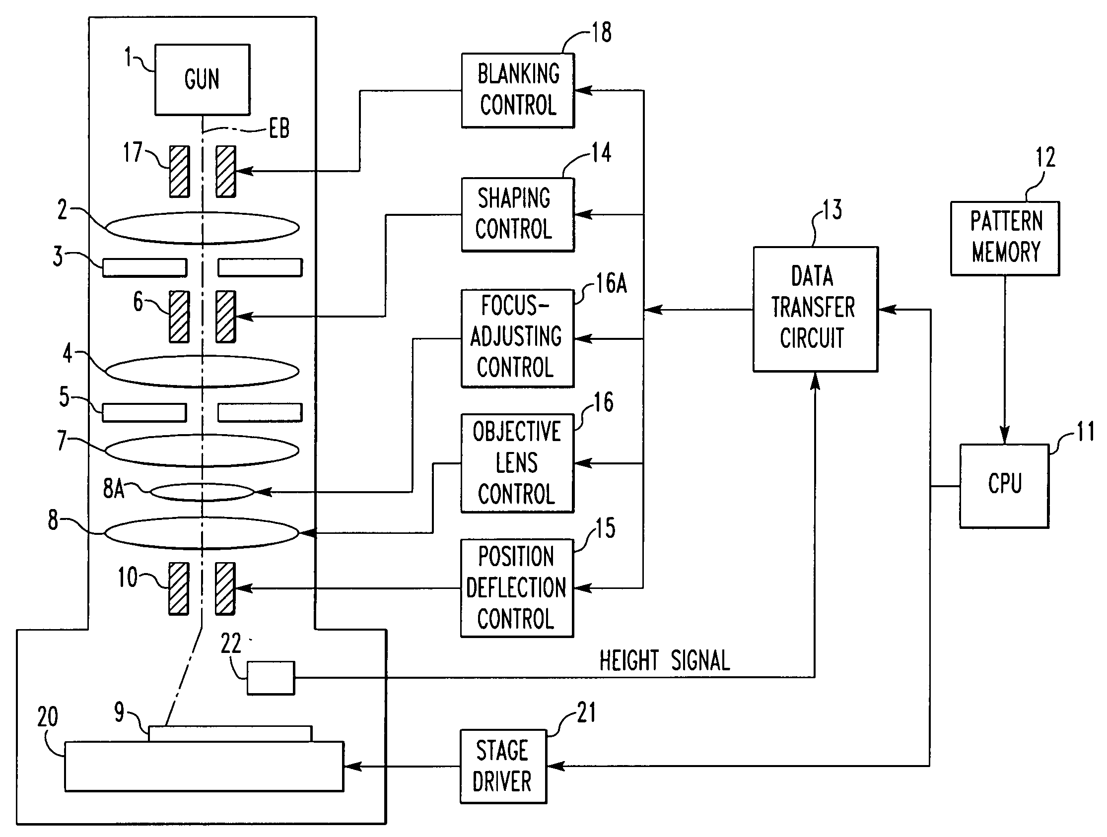
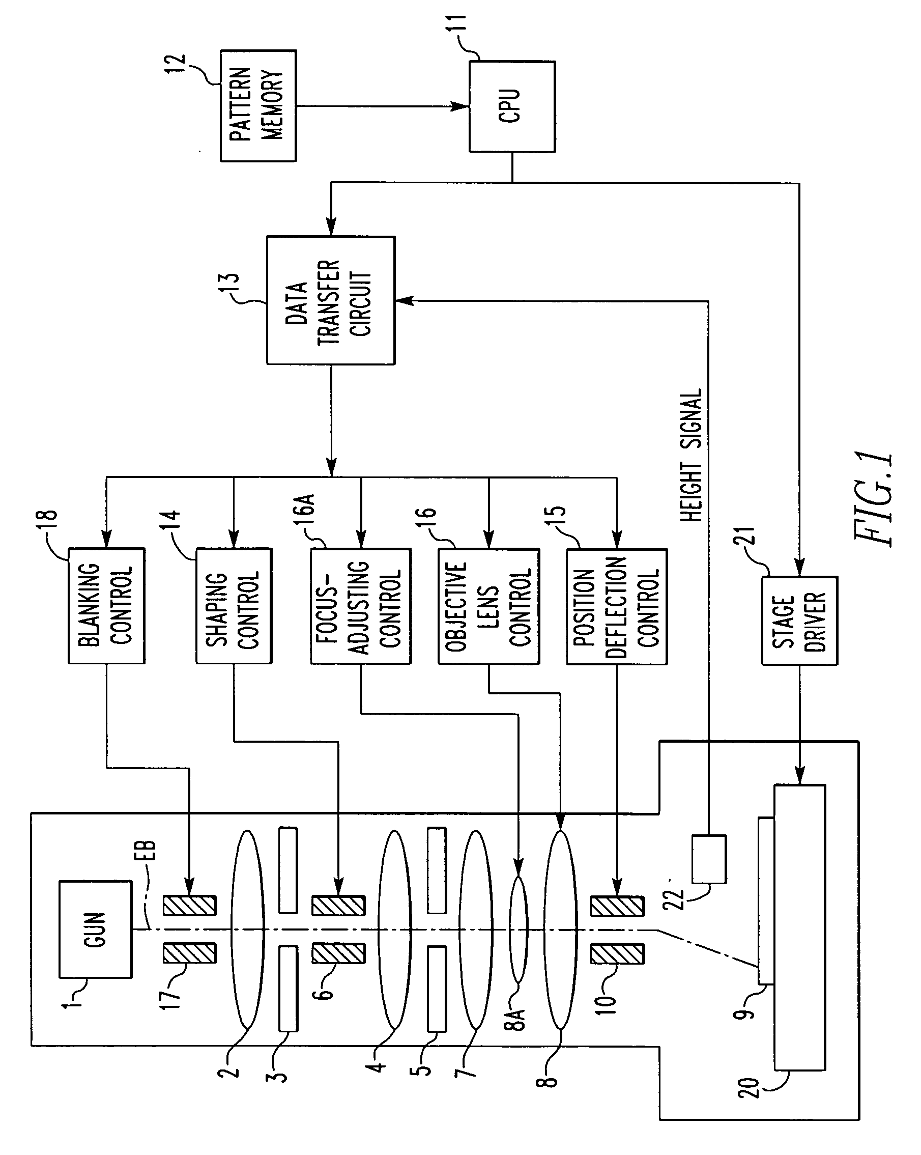
[0025] The preferred embodiments of the present invention are hereinafter described in detail with reference to the drawings. FIG. 1 shows a variable-area electron beam lithographic system for implementing the present invention. The system has an electron gun 1 producing an electron beam EB, which is directed onto a first shaping aperture (first slit) 3 via an illumination lens 2.

[0026] An image of the opening of the first shaping aperture is focused onto a second shaping aperture (second slit) 5 by a shaping lens 4. The position of the focused image can be varied by a shaping deflector 6. The image shaped by the second shaping aperture 5 is projected onto a workpiece 9 through a reduction lens 7, a focus-adjusting lens 8A, and an objective lens 8. The irradiation position on the workpiece 9 can be varied by a positioning deflector 10. The focus-adjusting lens 8A is a lens auxiliary to the objective lens 8, and is used to finely adjust the focus of the objective lens 8. For conveni...


PUM

PropertyMeasurementUnit
sizeaaaaaaaaaa
strengthaaaaaaaaaa
heightaaaaaaaaaa

Abstract

When the focal point of the objective lens of a charged-particle beam lithographic system is shifted according to the deflection position within a writing field, the image magnification of the objective lens will vary. In the present invention, the focal point of the objective lens is shifted in a corresponding manner to deflection positions in X- and Y-directions, respectively. Amounts of variations in the image magnification are previously measured, as well as the amounts of shifts. The results are stored in a memory. During lithographic writing, the focus of the objective lens is varied by referring to the memory according to the deflection positions. The size and position of a pattern to be written are corrected by controlling a shaping deflector and a positioning deflector.

Description

BACKGROUND OF THE INVENTION [0001] 1. Field of the Invention [0002] The present invention relates to a charged-particle beam lithographic system for writing a desired pattern on a mask substrate or silicon wafer by an electron beam or ion beam. [0003] 2. Description of Related Art [0004] An electron-beam lithographic system is used during a process in which a mask for creating semiconductor devices is fabricated. One example of this is a variable-area electron-beam lithographic system that writes a desired pattern by deflecting an electron beam while varying the cross-sectional area of the beam directed at a workpiece. In this system, the electron beam produced from the electron gun is directed at a first aperture having a rectangular opening. The beam transmitted through the first aperture is directed at a second aperture having a rectangular opening. [0005] A shaping deflector is disposed between the first and second apertures. The electron beam can be shaped into an arbitrary cro...

Claims


Application Information

Patent Timeline
Patent Type & Authority Applications(United States)
IPC IPC(8): G03F7/20G01K1/08G03F9/02H01J3/14H01J37/141H01J37/147H01J37/305H01J37/317H01L21/027
CPCB82Y10/00B82Y40/00G03F1/78H01J2237/31776H01J37/3174H01J2237/1536H01J2237/30461G03F7/2063
Inventor KOMAGATA, TADASHI
Owner JEOL LTD
Why Eureka
Try Eureka