High peak power laser cavity and assembly of several such cavities

a laser cavity and high-power technology, applied in the direction of laser details, active medium shape and construction, masers, etc., can solve the problems of complex and expensive laser, complex and expensive amplification system, complex and expensive optical amplifiers

Inactive Publication Date: 2005-06-02
COMMISSARIAT A LENERGIE ATOMIQUE ET AUX ENERGIES ALTERNATIVES
View PDF6 Cites 23 Cited by
  • Summary
  • Abstract
  • Description
  • Claims
  • Application Information

AI Technical Summary

Problems solved by technology

This results in a complex and expensive laser.
It also uses complex and expensive optical amplifiers.
which briefly describes a device with a very low power master oscillator outputting 1 mJ pulses at a maximum frequency of 1 kHz (therefore with an average power equal to not more than 1 W), followed by a complex and expensive amplification system.
However, up to now, all these attempts have failed.
The strict constraints in the specification obviously include the ability to generate high peak intensities with a very high recurrence rate.
The problem then arises that when the incident light power is low compared with the saturation fluence of the laser rod used (and particularly for incident fluences less than 200 mJ/cm2 for the Nd:YAG), the amplification provided by the rod is very weak.
A large number of amplifying rods which are extremely expensive are then necessary, together with several tens of diodes which are also very expensive, and the energy efficiency of the final result is very low.
This need to polarise the beam introduces an additional problem in the case in which the double pass amplification uses an isotropic material for example such as the Nd:YAG or the Yb:YAG, as the amplifying rod.
Thus, if complex devices were not installed to limit this phenomenon, polarisation

Method used


Image

  • High peak power laser cavity and assembly of several such cavities
  • High peak power laser cavity and assembly of several such cavities
  • High peak power laser cavity and assembly of several such cavities

Examples


Embodiment Construction

[0141] An optical resonator conform with the invention is shown in FIG. 5, and will be described in more detail later. It may be followed by one or several single pass amplifiers.

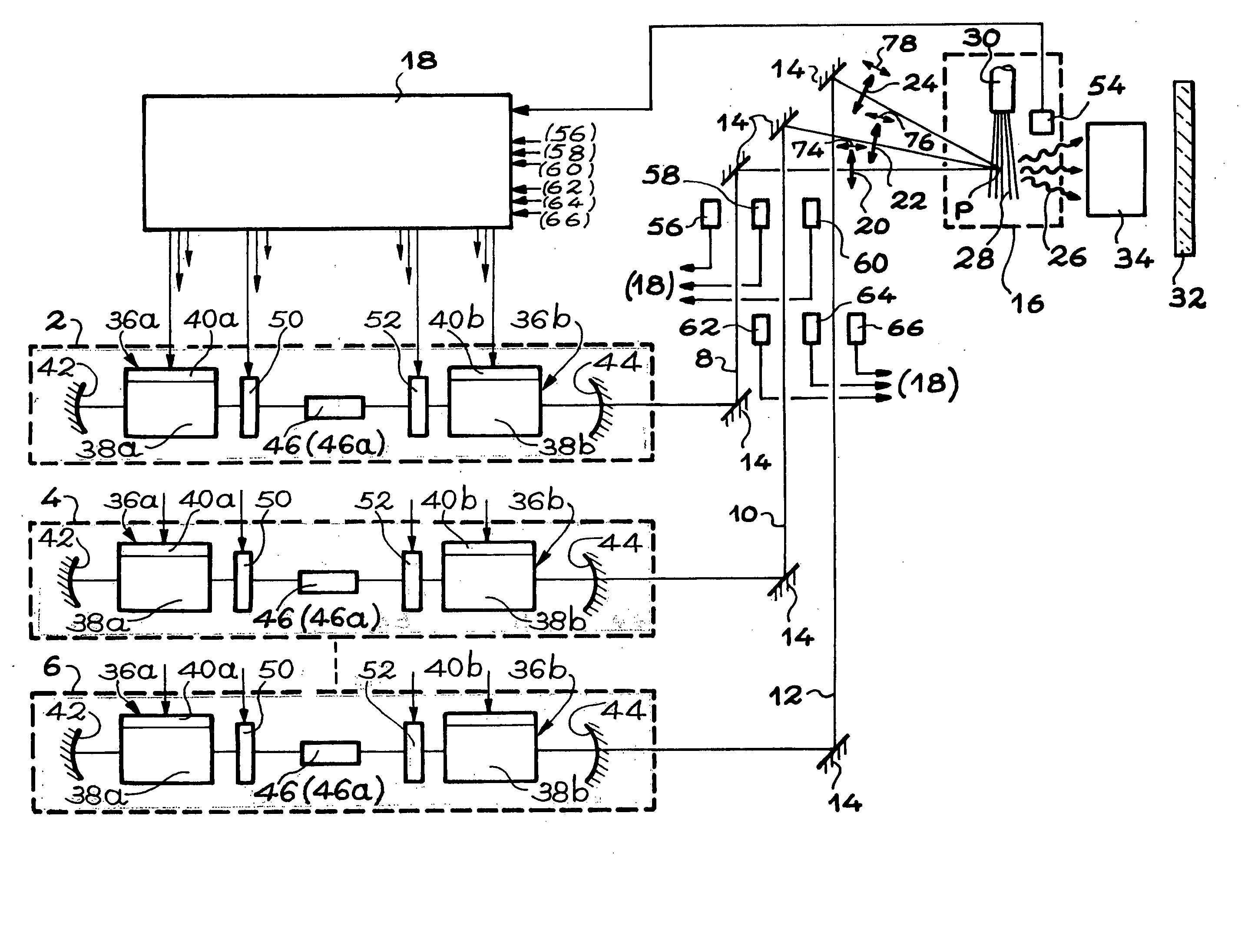
[0142] The combination of several pulsed optical resonators according to the invention in order to create an excitation device for a light source in the extreme ultraviolet is shown diagrammatically in FIG. 4.

[0143] The device in FIG. 4 comprises more than three pulsed optical resonators, that are also called pulsed lasers, for example ten, but only three of them are shown in this FIG. 4 and their reference numbers are 2, 4 and 6 respectively.

[0144] The light beams 8, 10 and 12 (more precisely the light pulses) supplied by these pulsed optical resonators 2, 4 and 6 were sent through a set of mirrors 14 to approximately the same point P on a target 16 and arriving at this point P at approximately the same time.

[0145] Laser control means 18 are also shown, capable of obtaining laser pulses.

[0146]FIG. 4 a...


PUM


Abstract

A high peak power optical rest and combination of plural of the resonators, particularly to excite a light generator in the extreme ultraviolet. An optical resonator with a solid state amplifying medium is pulsed and pumped by diodes operating continuously. The optical resonator includes at least two laser rods, at least one mechanism to trigger optical pulses, the triggering mechanism located in a part of a cavity in which the laser beam diverges least, and first and second mirrors that delimit the cavity, the first mirror being highly reflecting and the second mirror being partly reflecting.

Description

TECHNICAL DOMAIN [0001] This invention relates to a high peak power optical resonator with a high mean power and a high recurrence rate, with minimum cost and complexity. It also relates to the combination of several of these resonators, particularly to excite a light generator in the extreme ultraviolet. [0002] The invention is thus more particularly applicable to light generation in the extreme ultraviolet range. [0003] Radiation within this range that is also called “EUV radiation” has wavelengths varying from 8 nanometres to 25 nanometres. [0004] EUV radiation that can be obtained by making light pulses generated with the device according to the invention interact with an appropriate target has many applications, particularly in the science of materials, microscopy and more particularly microlithography to make very large scale integrated circuits. For very large-scale integrated circuits, it is particularly advantageous to have a high recurrence rate, which is very difficult to...

Claims


Application Information

Patent Timeline
IPC IPC(8): H01S3/117H01S3/23H01S1/00
CPCH01S3/07H01S3/0941H01S3/2383H01S3/127H01S3/117H01S3/05
Inventor THRO, PIERRE-YVESWEULERSSE, JEAN-MARCGILBERT, MICHEL
Owner COMMISSARIAT A LENERGIE ATOMIQUE ET AUX ENERGIES ALTERNATIVES
Why Eureka
Try Eureka