

Method and system to add high shear to improve an ionic liquid catalyzed chemical reaction
- Summary
- Abstract
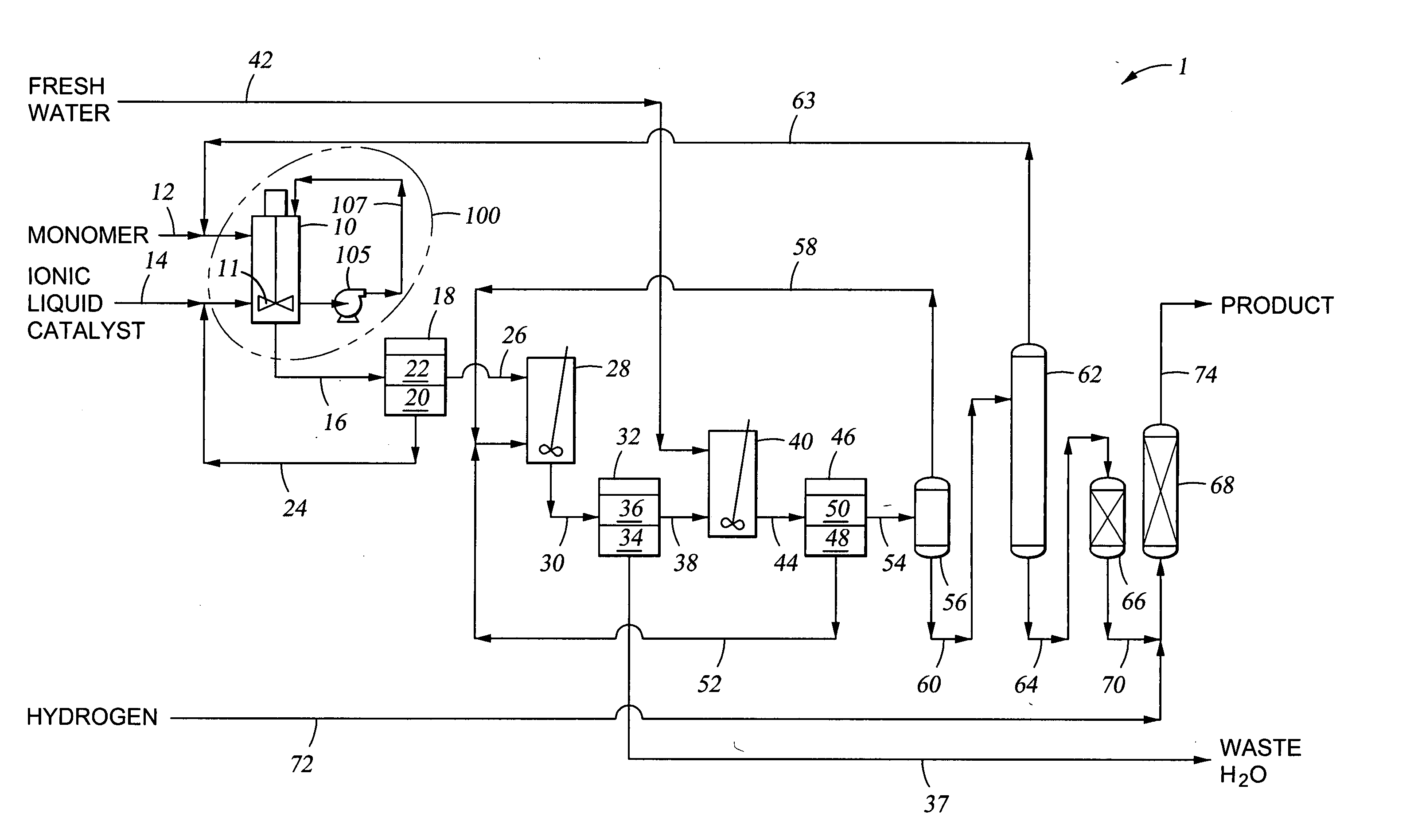
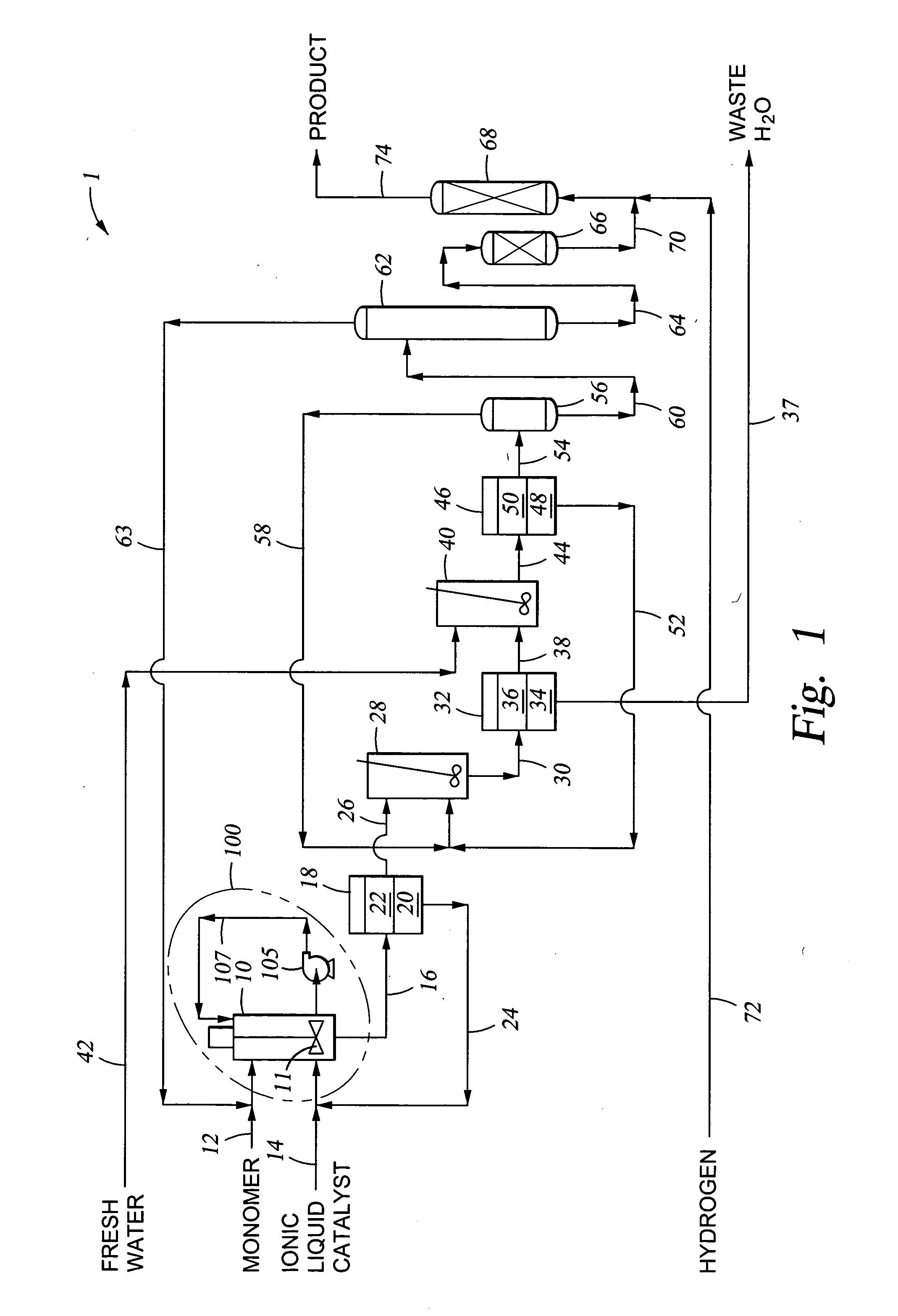
- Description
- Claims
- Application Information
AI Technical Summary
Benefits of technology
Problems solved by technology
Method used
Image

Examples
examples 1-3
High Shear Added in Oligomerization of 1-Decene
[0042] The following examples, examples 1-3, illustrate the effect of shear and high shear on some of the physical properties of the oligomer reaction product and the percentage of monomer converted in the reaction resulting from the continuous process for the oligomerization of 1-decene.
[0043] The shear rate data for each piece of mixing equipment used in the 3 examples was based on the fundamental calculation of velocity or tip speed divided by the distance or gap between the two surfaces. The one-gallon pilot plant reactor had an inside diameter of 5-inches. The reactor was equipped with a 2.5-inch radial six-blade impeller. A Tuthill gear pump housed two 0.5-inch diameter ten-teeth gears. A Silverson mixer (model 150 L) was equipped with a 1.5-inch diameter rotor. Table 2 below contains the specific information required to calculate the basic shear rate. For example, the reactor impeller shear rate calculation was based on: [0044]...
example 1
[0047] In a continuous process, 1-decene was fed at a rate of 3000 grams / hour along with a catalyst feed (1.65:1 molar ratio AlCl3:TMA.HCl) of 2.5 weight % into a 1-gallon stirred-tank reactor. The reactor was equipped with external and internal cooling coils. The 1-decene feed contained 31 to 61 ppm water. The reactor level was controlled to roughly half of the volume, which gave residence times from 27 to 30 minutes. The reactor was agitated with an internal stirrer operating at 432 ft / min tip speed. The reactor stirrer was set at 660 rpm. The reaction section was controlled from 19 to 22° C. under a headspace of 21% oxygen (balance nitrogen) at a pressure of 30 psig. The reactor effluent was quenched with water to deactivate the catalyst. The resulting product was distilled to a target monomer plus dimer content of less than about 2 weight percent. Monomer conversion of the water-quenched product was determined using gas chromatography. The percent monomer conversion of the water...
example 2
[0048] The conditions for Example 1 were repeated with the exception of the reactor agitation. In this example the reactor included a pump around loop with a Tuthill gear pump model no. 9174S with a tip speed of 236 ft / min. As shown below in Table 3, the increase in shear rate results in enhanced 1-decene conversion and viscosity.
PUM
| Property | Measurement | Unit |
|---|---|---|
| Temperature | aaaaa | aaaaa |
| Fraction | aaaaa | aaaaa |
| Diameter | aaaaa | aaaaa |
Abstract
Description
Claims
Application Information