Projection lens

a projection lens and lens body technology, applied in the field of projection lenses, can solve the problems of small distortion aberration in the projection lens that cannot be electrically corrected due to dot matrix display, hinders the realization of the wide angle of view and the long back, and the positional shift of the back focus due to temperature change, etc., to achieve finer images, reduce the increase of refractive index by decreasing wavelength, and achieve high focusing performance

Inactive Publication Date: 2005-06-09
SEKINOSU
View PDF3 Cites 4 Cited by
  • Summary
  • Abstract
  • Description
  • Claims
  • Application Information

AI Technical Summary

Benefits of technology

[0016] A wide angle of view, high focusing performance, and a finer image can be realized by forming the projection lens in the above-described way.
[0017] It is desirable that the first lens, the second lens, and the fourth lens are molded with a synthetic resin respectively, and Abbe numbers of these lenses ν1, ν2, and ν4 satisfy ν1, ν2, and ν4>54, and the Abbe numbers of the sixth and seventh lenses ν6 and ν7 satisfy ν6 and ν7>68. Therefore, when the condition of the Abb numbers is satisfied, an increase in refractive index by decrease in wavelength can be reduced.
[0018] It is desirable that the negative refractive power of the first and second lenses and the positive refractive power of the fourth lens have values which suppress positional shift of back focus due to temperature change by canceling out each other. Therefore, when the temperature is changed, the positional shift of the back focus by the first and second lenses and the positional shift of the back focus by the fourth lens are generated in the opposite directions to each other while the values of the positional shifts are substantially similar to each other, so that the positional shifts are suppressed by canceling out each other.

Problems solved by technology

Unlike a CRT (Cathode Ray Tube) method, in the liquid crystal light valve, distortion aberration can not be electrically corrected due to dot matrix display.
However, the realization of the small distortion aberration in the projection lens becomes hinders in realizing the wide angle of view and the long back focus of the projection lens.
However, in the case of the above-described acryl resin lens, there is a problem that positional shift of the back focus (change in focusing surface) due to temperature change is large.
Since these values are larger than a pixel size of a 15 μm by 15 μm square of the current image display device, there is a problem that color shift is generated toward a periphery in the projected image.

Method used


Image

  • Projection lens
  • Projection lens
  • Projection lens

Examples


first embodiment

[0055] Referring to the accompanying drawings, a projection lens according to a first embodiment of the invention will be described below.

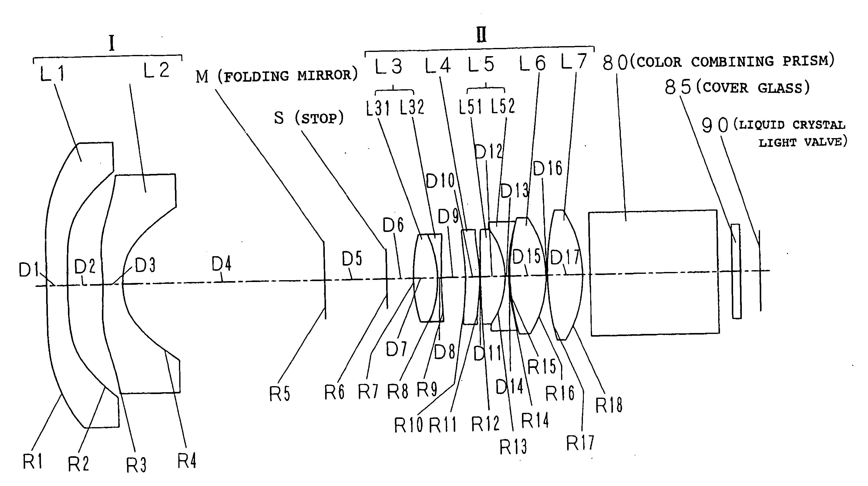
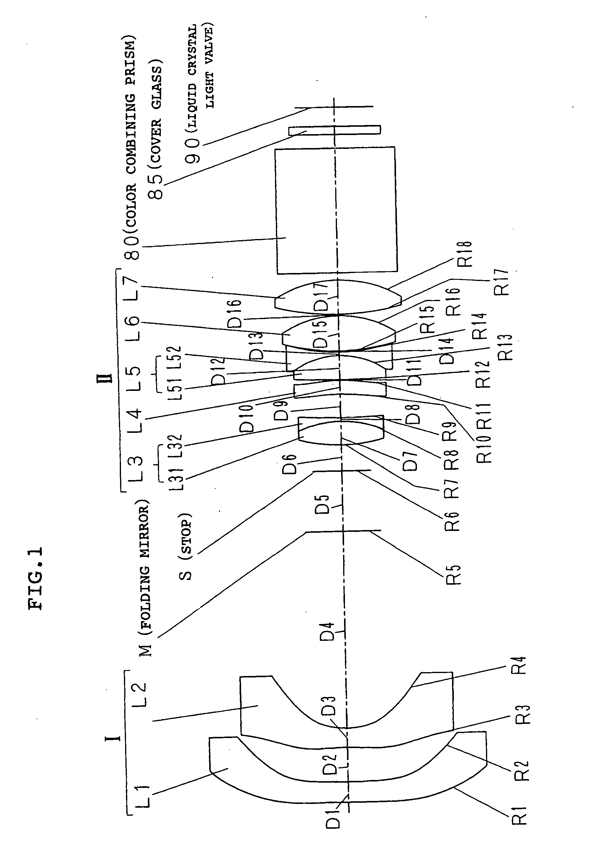
[0056] As shown in FIG. 1, the projection lens according to the first embodiment is one which magnifies and projects a color image of a liquid crystal light valve 90 which is of a transmission type image display device on a screen (not shown) provided on the left side of FIG. 1. Hereinafter the side of the screen is referred to as “magnified side” and the side of the transmission type image display device such as the liquid crystal light valve 90 is referred to as “reduced side”.

[0057] In FIG. 1, the projection lens is configured to arrange a first group I having a negative refractive power and a second group II having a positive refractive power in order from the magnified side toward the reduced side. A color combining prism 80, a cover glass 85, and the liquid crystal light valve 90 are provided on the reduced side of the second group II.

[00...

example 1

[0072] For the projection lens of the first embodiment, Example 1 will be described below using specific numerical values.

[0073] As shown in FIG. 1, it is assumed that a curvature radius of an ith surface from the magnified side is set to Ri and a surface interval on an optical axis between the ith surface and a (i+1)−th surface is set to Di. The values of the d line are used for the refractive index and the Abbe number. The focal distance of the whole system is represented by f (value of the e line), the brightness is represented by F / no, the angle of view is represented by 2ω, the lateral magnification is represented by M, and the projection distance is represented by L.

[0074] As is well known, in the aspheric surface, when R is set to a paraxial curvature radius, K is set to a conical constant, A3, A4, . . . , and A14 are set to tertiary, quartic, and four-teenth-order aspheric constants respectively in a Cartesian coordinate (X, Y, Z) in which the optical axis is set to the Z ...

example 2

[0080] For the projection lens of the first embodiment, Example 2 will be described below using specific numerical values.

[0081] The definitions of the curvature radius Ri, the surface interval Di on the optical axis, and the like are set in the same way as Example 1.

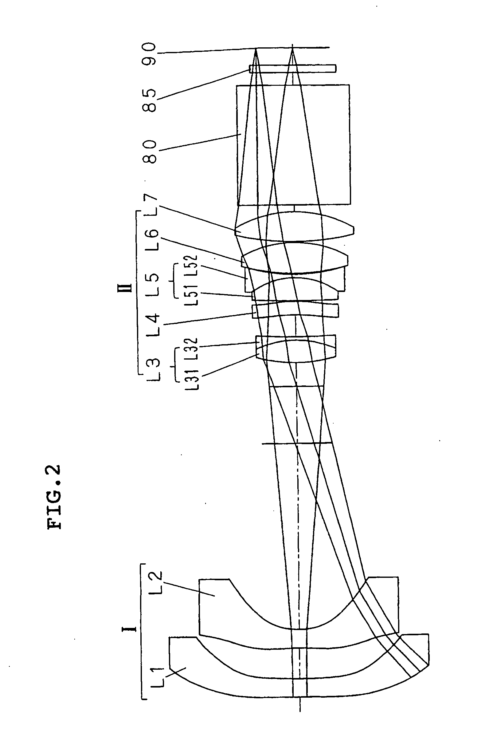
[0082] In Example 2, the lens configuration and the ray tracing are substantially similar to Example 1 of FIG. 2.

[0083] In Example 2, the focal distance f is set to 10.76 mm, the brightness F / no is set to 2.41, the back focus BFL is set to 37.581 mm, the angle of view 2ω is set to 91.1°, the lateral magnification M is set to −1 / 74.74×, and the projection distance L is set to 768.0 mm.

[0084]FIG. 5 shows the result of the lens design by the above-described setting, and FIG. 6 shows the result of the simulations of various kinds of the aberration in the lens design of FIG. 5. As can be seen from a graph in FIG. 6, the good results are obtained in the spherical aberration, the astigmatism, the distortion aberration, and...


PUM


Abstract

An object of the present invention is to suppress an influence due to temperature change and various aberrations. It is a projection lens which projects an image on a surface of a screen (magnified side). A first group I having a negative refractive power and a second group II having a positive refractive power are arranged in order from a magnified side toward a reduced side. The first group I is configured to arrange a first lens and a second lens in order from the magnified side, and the second group II is configured to arrange a third lens to a seventh lens. The first and second lenses are a negative meniscus lens whose both surfaces are formed by the aspherical surface in which an area near an optical axis of the surface on the magnified side is a concave surface. The third lens is a cemented lens in which a bi-concave lens is cemented to the surface on the reduced side of a bi-convex lens. The fourth lens is a positive meniscus lens whose both surfaces are formed by the aspherical surface, and a convex surface of the positive meniscus lens faces toward the reduced side. The fifth lens is the cemented lens in which the bi-concave lens is cemented to the surface on the reduced side of the bi-convex lens. The sixth lens is a positive lens whose strong convex surface faces toward the reduced side. The seventh lens is the positive lens whose both surfaces are a convex surface.

Description

CORSS-REFERENCE TO RELATED APPLICATION [0001] This application claims, under 35 USC 119, priority of Japanese Application No. 2003-399708 filed Nov. 28, 2003 and Japanese Application No. 2004-337187 filed Nov. 22, 2004. BACKGROUND OF THE INVENTION [0002] 1. Field of the Invention [0003] The present invention relates to a projection lens, particularly to a projection lens suitable for a rear projection type image display apparatus. [0004] 2. Description of the Related Art [0005]“A rear projection type image display apparatus”, in which a white light beam emitted from a white light source is separated into color components of three primary colors, a transmission type or a reflection type of image display device is lit with each separated color component light beam, each color component light beam transmitted through or reflected from each color component of the image display device is combined with a color combining system, and a color image is displayed by performing projection on a ...

Claims


Application Information

Patent Timeline
Patent Type & Authority Applications(United States)
IPC IPC(8): G02B13/16G02B13/18G02B13/04G02B13/22H04N5/74
CPCG02B13/22G02B13/18G02B13/0045G02B13/0095G02B13/16G02B3/02G02B3/0043
Inventor KOBAYASHI, TAKESHISEKINE, KUMAJIRO
Owner SEKINOSU
Why Eureka
Try Eureka