Combustion-engine air-intake ozone and air ion generator

a technology of air intake and generator, which is applied in the field of combustion engines, can solve the problems of inability to generate the concentrations necessary for health or industrial applications, inability to generate ozone in high volumes even with oxygen feed, and humidity in the intake air to reduce the effectivity of corona discharge ozone generator, etc., to achieve simple, inexpensive and effective installation, and increase passenger car fuel efficiency.

Inactive Publication Date: 2005-06-16
VARASUNDHAROSOTH BIRASAK +1
View PDF21 Cites 42 Cited by
  • Summary
  • Abstract
  • Description
  • Claims
  • Application Information

AI Technical Summary

Benefits of technology

[0012] An advantage of the present invention is a device is provided to increase passenger car fuel efficiency.
[0013] Another advantage of the present invention is that a power boosting device is provided that is simple, inexpensive, and effective.
[0014] A still further advantage of the present invention is that a power boosting device is provided that is quick and simple for a typical user to install.
[0015] Another advantage of the present invention is an engine power booster is provided that requires no modifications to the engine on which it is installed.
[0016] The above and still further objects, features, and advantages of the present invention will become apparent upon consideration of the following detailed description of specific embodiments thereof, especially when taken in conjunction with the accompanying drawings.

Problems solved by technology

But, UV techniques cannot generate high volumes of ozone even with oxygen feed, e.g., not more than 1-3 micrograms of ozone per milliliter of oxygen.
However, humidity in the intake air reduces the effectivity of corona discharge ozone generators, while UV-type ozone generators are little affected by water vapor.
But, UV cannot generate the concentrations necessary for health or industrial applications, even with oxygen feed.
It is the most cost effective way to produce large quantities of ozone, but reliability is always a problem.
An improved variation is called dual-dielectric, used for medical purposes, but long term reliability is again problematic.

Method used


Image

  • Combustion-engine air-intake ozone and air ion generator
  • Combustion-engine air-intake ozone and air ion generator
  • Combustion-engine air-intake ozone and air ion generator

Examples


Embodiment Construction

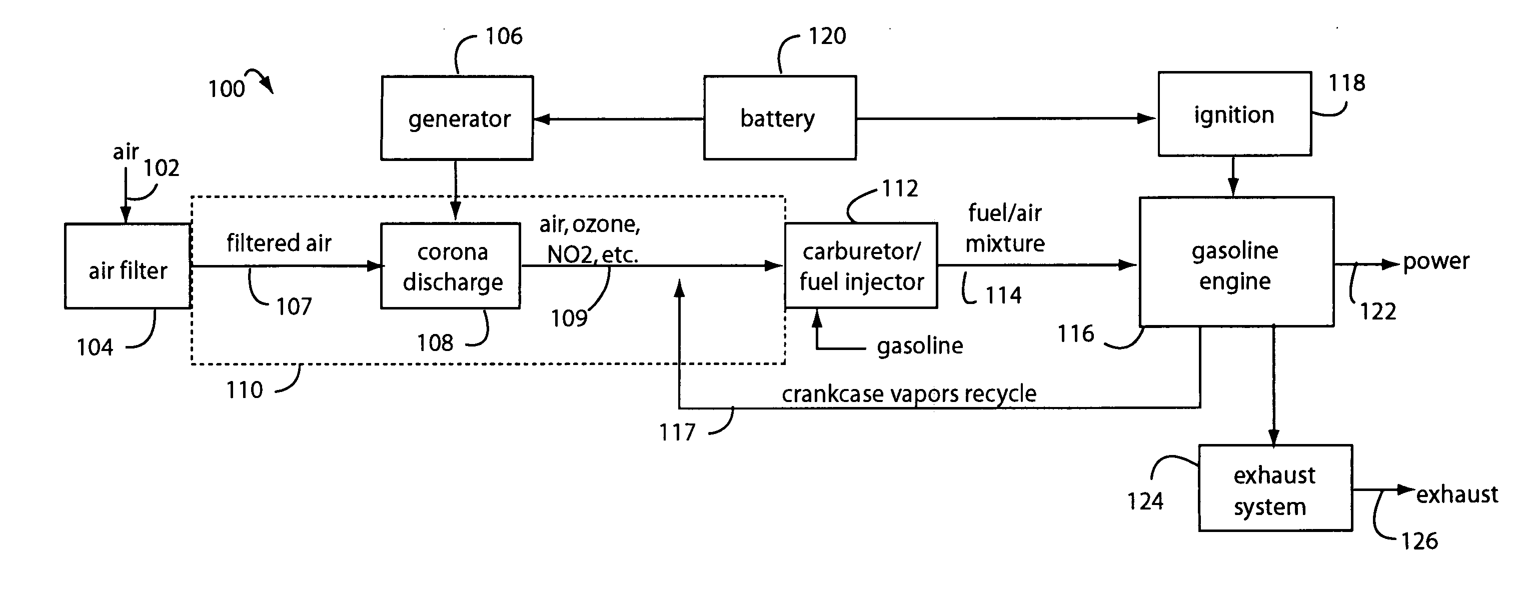
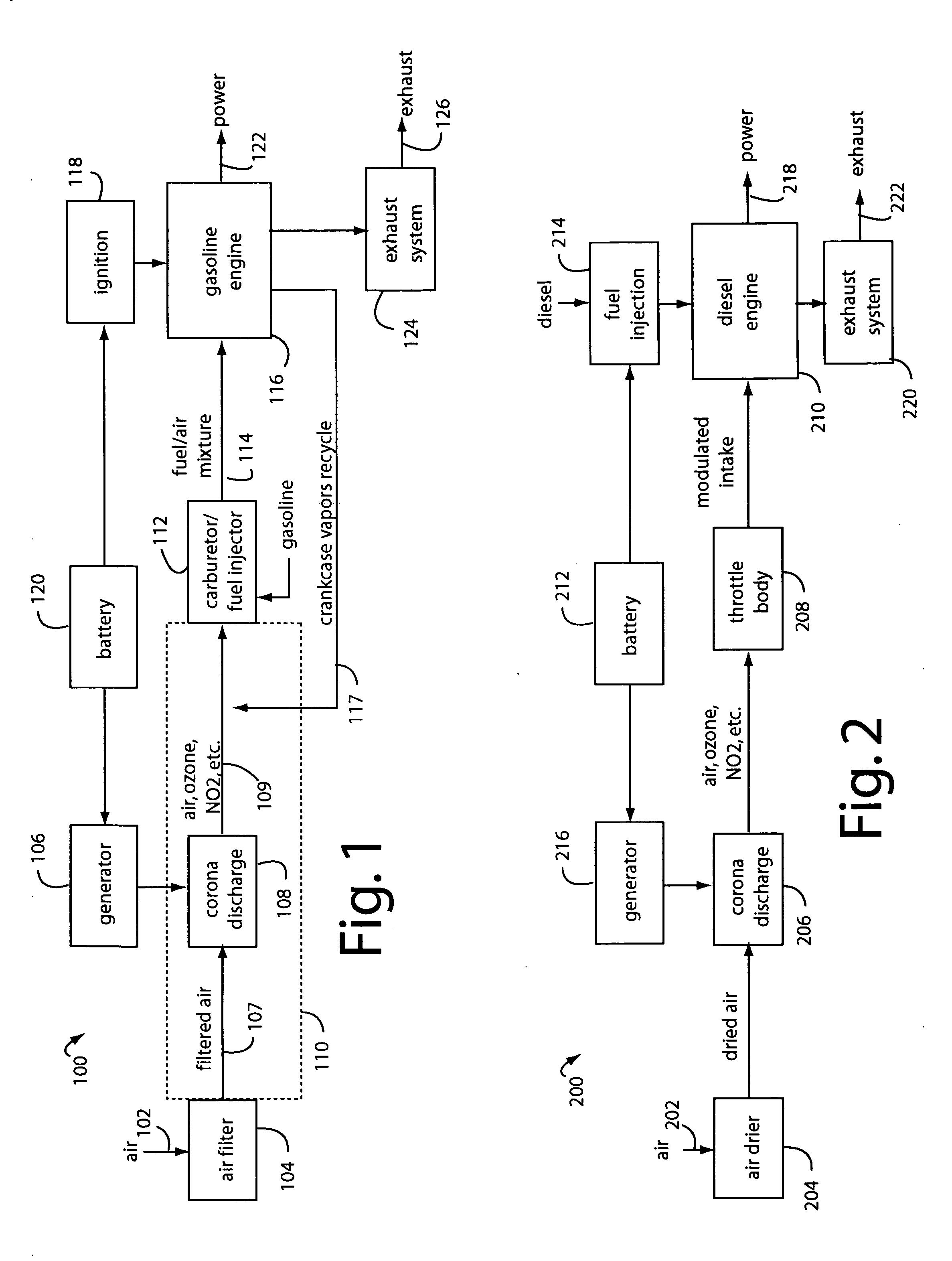
[0021]FIG. 1 illustrates a gasoline engine system embodiment of the present invention, and is referred to herein by the general reference numeral 100. The system 100 comprises a fresh air intake 102, an air filter 104, and a high-voltage generator 106 connected to a corona discharge electrode 108 positioned inside an air intake duct 110. In a typical automobile, the air filter 104 is remote from a carburetor / fuel-injector 112 and the duct 110 is a long plastic or fiberglass tube about twenty inches long and a couple of inches in diameter. The carburetor 112 provides a fuel / air mixture 114 to an internal combustion engine 116. As is typical in applications with smog control, blow-by and other crankcase vapors 117 are returned to the duct 110 to be reburned. It is important that the corona discharge electrode 108 be upstream of the point where these vapors 117 are injected into the duct 110. Such vapors would otherwise foul the electrode.

[0022] The system 100 further comprises an ele...


PUM


Abstract

An engine power booster comprises an electronic voltage generator that converts the direct current (DC) battery voltage of a vehicle at a power input, into an AC ripple voltage of 2.8-5.0 KV peak-to-peak at 2.4-14.0 KHz, that includes a DC voltage of 2.0-3.5. KV which are provided at an electrode output. A wire electrode is connected to the electrode output, and comprises a simple insulated stranded wire stripped bare at a distal end. A corona discharge generates ozone at the distal end during operation inside an internal combustion engine's air intake duct. Such ozone intake increases engine power and fuel efficiency.

Description

BACKGROUND OF THE INVENTION [0001] 1. Field of the Invention [0002] The present invention relates to combustion engines, and more particularly to improvements in performance that result from corona discharge treatment of their air intakes. [0003] 2. Description of Related Art [0004] Internal combustion engines depend on the oxidizing of hydrocarbons. Ozone is one of the most powerful oxidants. Ozone is produced naturally by ultra-violet (UV) rays of the sun and lightning. Ozone can also be generated artificially by UV-lamps, cold-corona discharge, and Teslaire cold-plasma. The first simulates the action of the sun, and the latter two simulate lightning. UV-light in the 180-90 nanometer frequency will generate ozone from ambient air without producing nitrous oxide compounds. But, UV techniques cannot generate high volumes of ozone even with oxygen feed, e.g., not more than 1-3 micrograms of ozone per milliliter of oxygen. However, humidity in the intake air reduces the effectivity of...

Claims


Application Information

Patent Timeline
Patent Type & Authority Applications(United States)
IPC IPC(8): F02M25/08F02M27/04
CPCF02M25/0836F02M25/0854Y02T10/121F02M25/12F02M27/04F02M25/0872Y02T10/12
Inventor VARASUNDHAROSOTH, BIRASAKPHANICHAMNUAY, SOMROJ
Owner VARASUNDHAROSOTH BIRASAK
Why Eureka
Try Eureka