Heat transport device and electronic device

a technology of electronic devices and heat transport devices, which is applied in the direction of semiconductor devices, lighting and heating apparatus, basic electric elements, etc., can solve the problems of vapor hindered by liquid, heat transport efficiency may decline, and heat transport efficiency and ability can be reduced, so as to improve the capillary force of liquid channels, reduce pressure loss, and stable operation

Inactive Publication Date: 2005-06-16
SONY CORP
View PDF13 Cites 18 Cited by
  • Summary
  • Abstract
  • Description
  • Claims
  • Application Information

AI Technical Summary

Benefits of technology

[0016] Accordingly, it is an object of the present invention to provide a compact and thin heat transport device that achieves high heat transport ability and high heat transport efficiency.
[0018] A plurality of liquid channels can prevent the performance deterioration and malfunction of the device due to the entry of vapor-phase working fluid into the liquid channels. For example, even if the circulation of liquid-phase working fluid is hindered by the entry of vapor-phase working fluid into one liquid channel, the liquid-phase working fluid is supplied to the wick through the remaining well-conditioned liquid channels, and therefore, dryout or the like can be prevented. As a result, the heat transport ability and efficiency can be enhanced.
[0020] This can increase the capillary force of the liquid channels, and can prevent vapor-phase working fluid from entering the liquid channels. Consequently, even after dryout is caused by excessive input, the wick and the liquid channels adjacent thereto are filled with liquid-phase working fluid, and therefore, stable operation can be achieved.
[0021] In a case in which a plurality of liquid channels are provided, and the cross-sectional areas of the liquid channels gradually decrease from the condenser toward the evaporator, it is possible to reduce pressure loss caused by the flow of liquid-phase working fluid in the liquid channels.

Problems solved by technology

However, the known devices have the following problems with the heat transport efficiency and ability.
In a heat transport system including an evaporator and a condenser, when vapor in the vapor channel radiates heat and condenses into a liquid phase before reaching the condenser, the movement of the vapor is hindered by the liquid, and the heat transport efficiency may decline.
When liquid in the liquid channel is vaporized by heat from the outside before reaching the evaporator, the movement of the liquid is hindered by the vapor, and the heat transport efficiency may decline.
In particular, when the device is restarted after dryout (a phenomenon in which the evaporator gets dry) is caused by excessive thermal input, working fluid is not supplied to the wick, and as a result, the heat transport device may not work.
However, this method complicates the configuration of the heat transport device, and cannot be similarly applied to small heat transport devices in which channels for working fluid are provided in a substrate.
In such devices that attach importance to a small and thin structure, few means have been taken to suppress the heat exchange with the outside, and therefore, the heat transport efficiency is decreased.

Method used


Image

  • Heat transport device and electronic device
  • Heat transport device and electronic device
  • Heat transport device and electronic device

Examples


Embodiment Construction

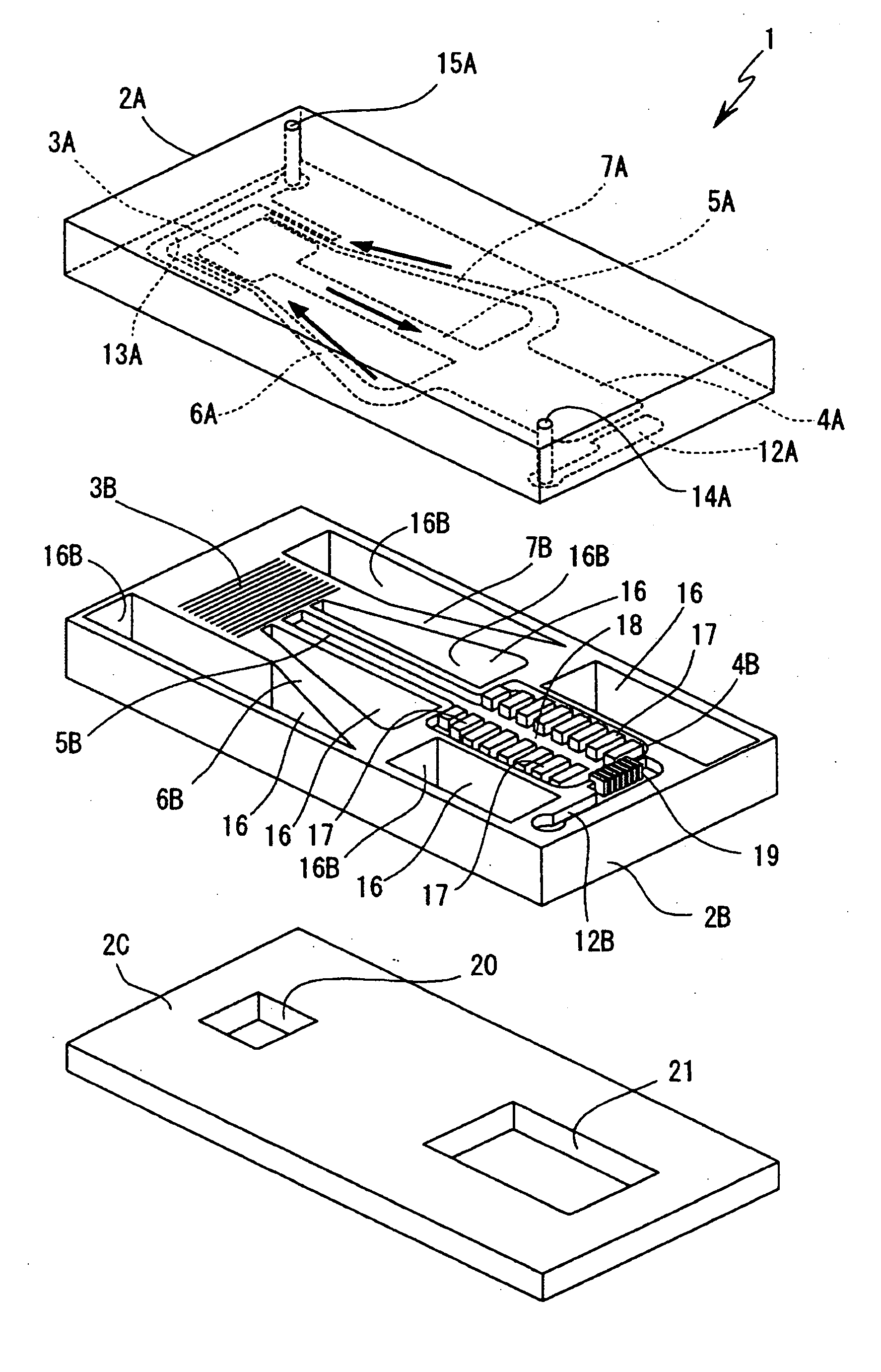
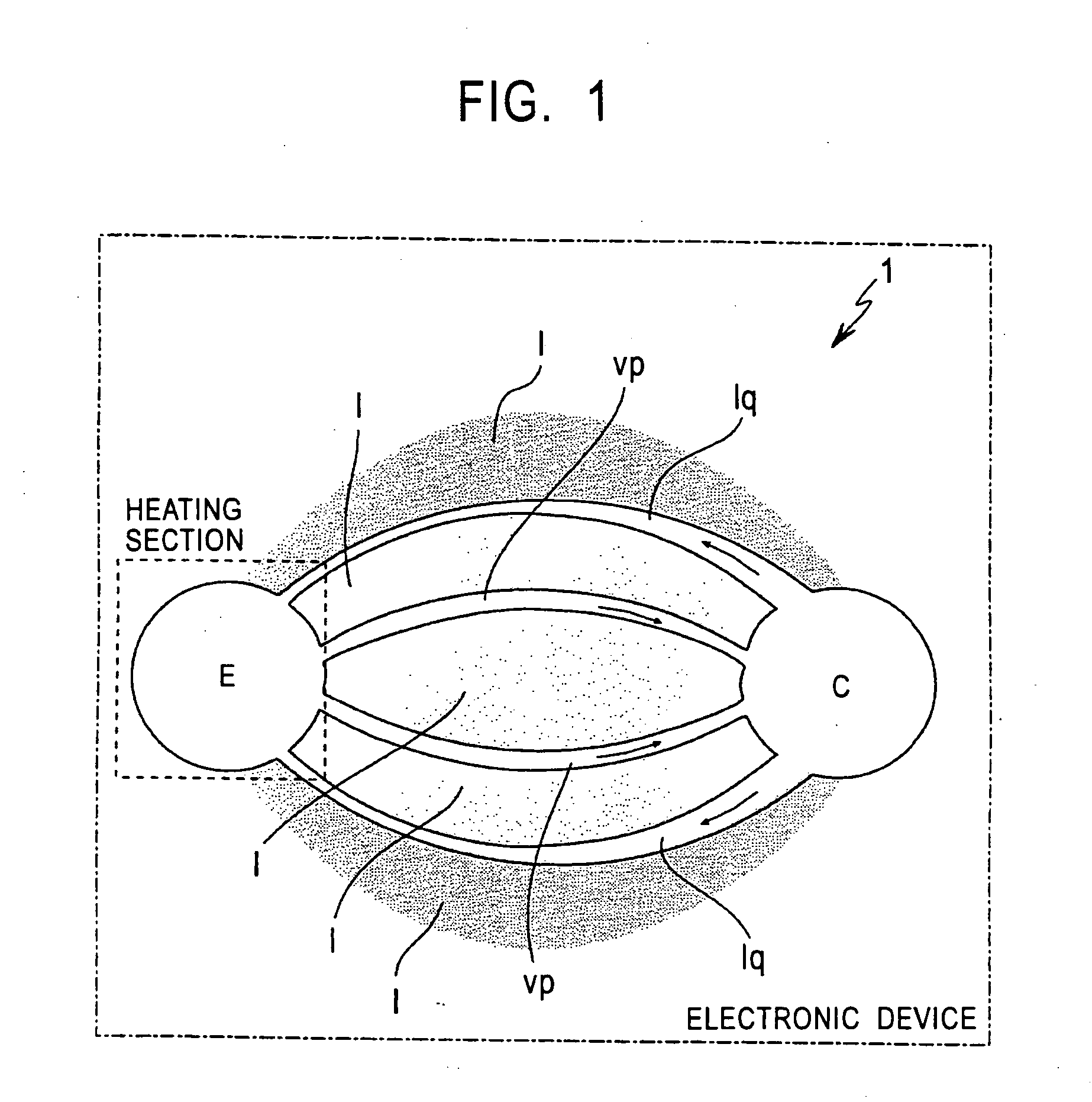
[0032] A heat transport device of the present invention is suitably used for devices using a capillary pumped loop, a loop heat pipe, and the like, and is applicable to radiating and cooling systems in various electronic devices. For example, in applications to information processing devices, such as computers, portable devices, and the like, the heat transport device is effective in enhancing the efficiency of radiation and cooling of various devices (e.g., CPUs, image pickups, light emitting elements, driving motors for use in small hard disk drives and drives for optical media, and actuators used in a thermally strict condition) without increasing the size and thickness of the devices.

[0033] Herein, the “heat transport device” means, in a narrow sense, a device for transporting heat from a heating element with working fluid or the like, but means, in a broad sense, the entire system including a heating element, a cooling or radiating means, a temperature controller, and so on.

[...


PUM


Abstract

A heat transport device includes an evaporator, a condenser, and a vapor channel and a plurality of liquid channels that connect the evaporator and the condenser. The evaporator generates a capillary force to circulate working fluid. This structure prevents the performance deterioration and malfunction due to the entry of vapor-phase working fluid into the liquid channels. Since the cross-sectional areas of the liquid channels gradually decrease from the condenser toward the evaporator, the capillary force at the liquid channels can be increased, and vapor-phase working fluid is prevented from entering the liquid channels. Wicks and the portions of the liquid channels adjacent thereto are filled with liquid-phase working fluid even after dryout occurs, stable operation is achieved.

Description

BACKGROUND OF THE INVENTION [0001] 1. Field of the Invention [0002] The present invention relates to a heat transport device having an evaporator and a condenser, and an electronic device. More particularly, the present invention relates to a heat transport technique that achieves size and thickness reduction by using a CPL (capillary pumped loop), a loop heat pipe, or the like in the field of fluid MEMS (micro-electro-mechanical systems). [0003] 2. Description of the Related Art [0004] Various devices (e.g., heat pipes, heat sinks, and radiating fins) are widely used for heat radiation and cooling. Because of recent advances in the electronic device technology and micromachining technology, compact devices can be produced. For the production of such compact devices, so-called MEMS technology using a semiconductor manufacturing technology has received attention, and studies have been made to apply the MEMS technology to heat transport devices. This is because heat-source cooling sys...

Claims


Application Information

Patent Timeline
Patent Type & Authority Applications(United States)
IPC IPC(8): F28D15/04H01L23/427F28D15/02
CPCF28D15/043H01L23/427H01L2924/0002H01L2924/00F28D15/02
Inventor MAKINO, TAKUYAHARA, MASAKI
Owner SONY CORP
Why Eureka
Try Eureka