
System and method for custom-polarized photolithography illumination

a photolithography and custom-polarized technology, applied in the field of custom-polarized photolithography illumination, can solve the problems of significant contrast loss, significant contrast reduction, and decrease in the resolution of the system

Active Publication Date: 2005-06-16
TEXAS INSTR INC
View PDF6 Cites 63 Cited by
  • Summary
  • Abstract
  • Description
  • Claims
  • Application Information

AI Technical Summary

Benefits of technology

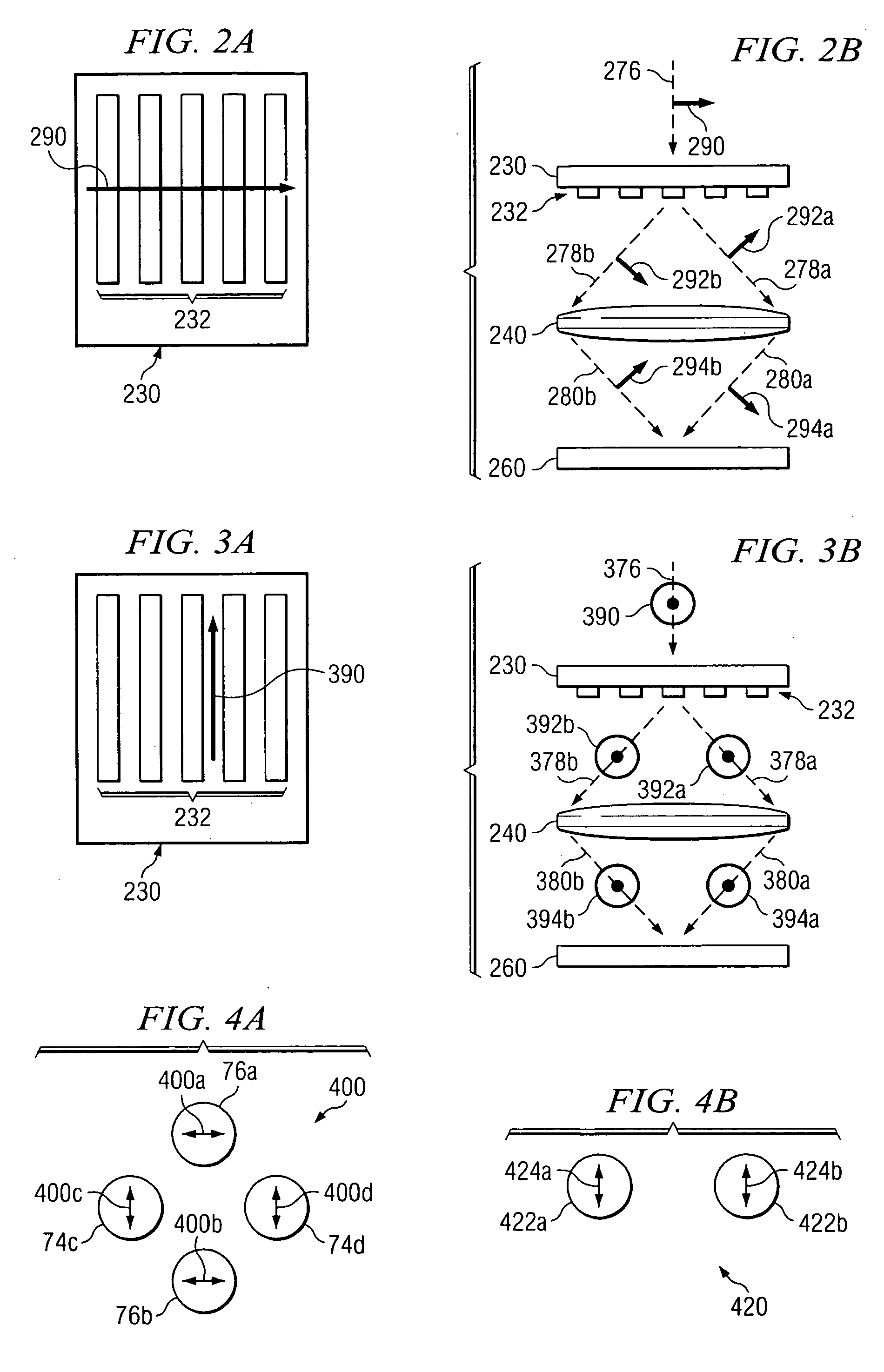
[0005] Technical advantages of one or more embodiments of the present invention may include the ability to vary the polarization of light specific to a desired illumination pattern to be projected onto the wafer. The polarization may be variable with respect to different light beams in the illumination pattern and / or different portions of a single light beam. Another technical advantage of one embodiment of the present invention is to provide for variable polarization of light to provide optimum line and space printing of a photolithographic image, thereby allowing for smaller images to be printed than are possible using conventional photolithography techniques. Still another technical advantage of the present invention is the ability to print photolithographic images in two directions using a single mask during a single exposure to the variably polarized light.

Problems solved by technology

In the case of unpolarized or circularly polarized illumination, interference of electrical fields exacerbated by Brewster angle effects can lead to a significant reduction in contrast for the resulting photolithographic image, decreasing the resolution of the system.
In systems where light is linearly polarized, significant contrast loss may prevent geometry from being printable on the wafer.

Method used


Image

  • System and method for custom-polarized photolithography illumination
  • System and method for custom-polarized photolithography illumination
  • System and method for custom-polarized photolithography illumination

Examples


Embodiment Construction

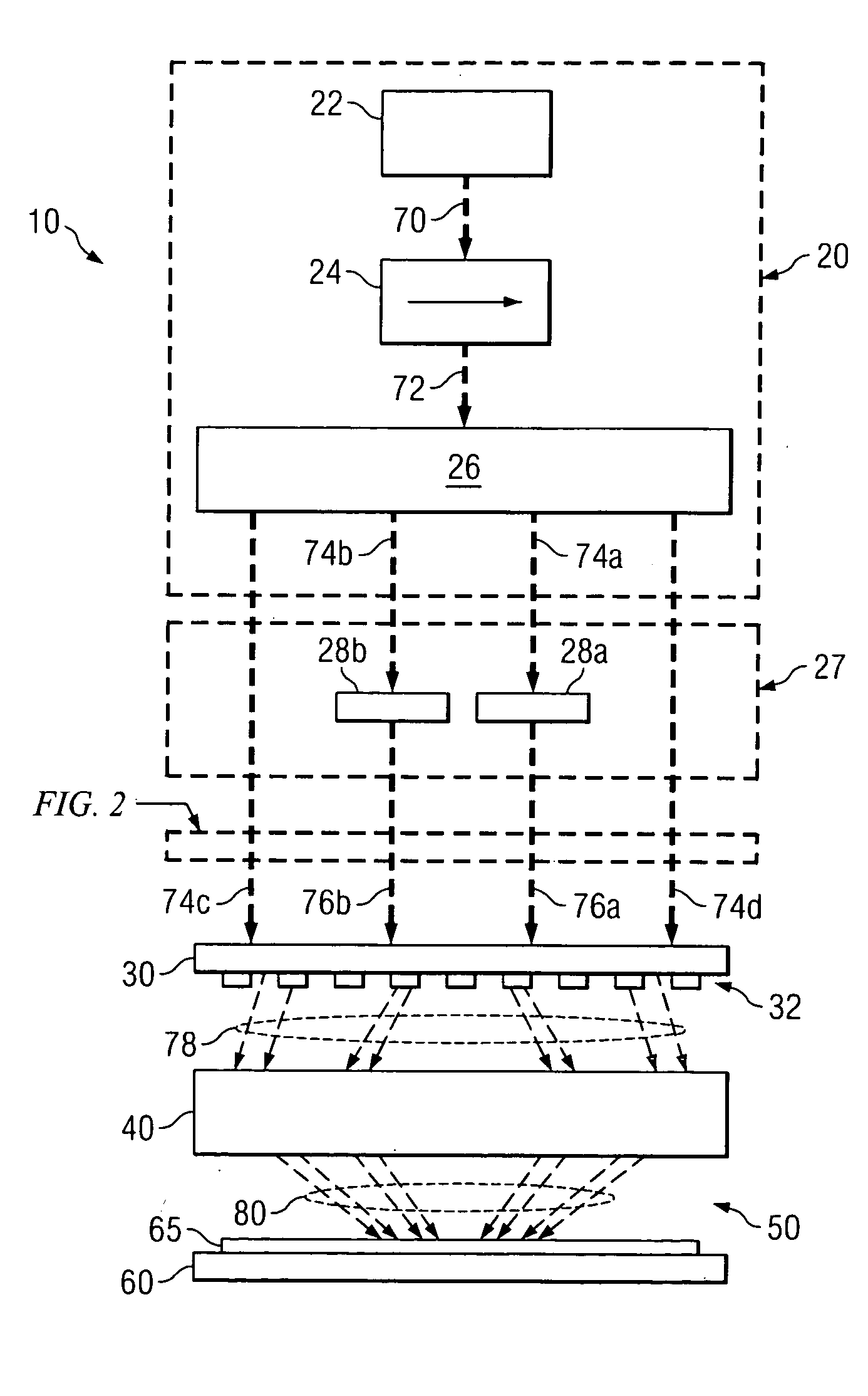
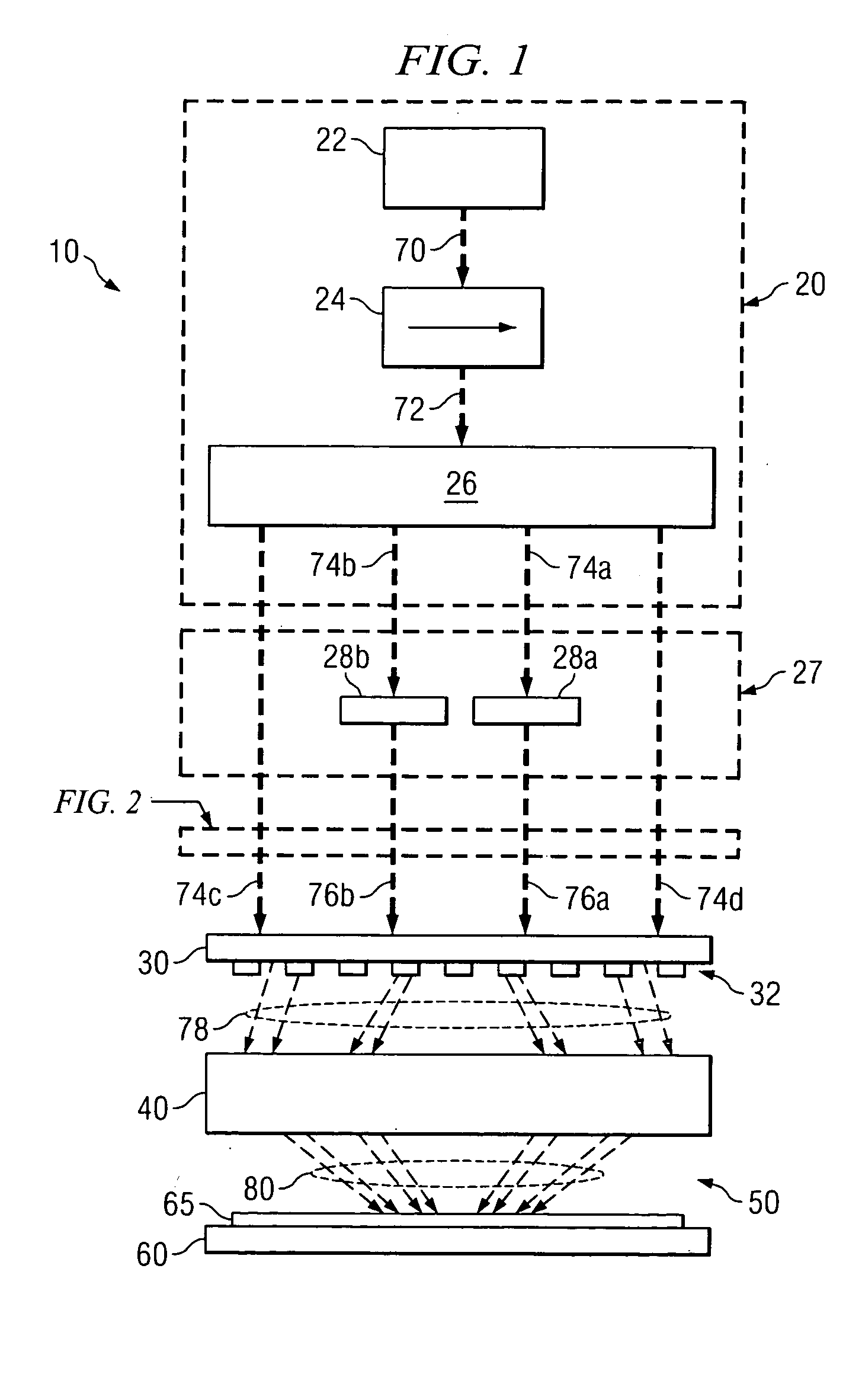
[0013]FIG. 1 illustrates an example system 10 for generating a photolithographic image using variably polarized light. System 10 may include an illuminator 20, a polarizer unit 27, a mask 30, a projection lens system 40, a medium 50, and a wafer 60. In certain embodiments, illuminator 20 may comprise a light source 22, a polarizer 24, and a prism system 26. Light source 22 may comprise any device or combination of devices capable of generating light used to create a photolithographic image. As used throughout this disclosure and the following claims, the term “light” refers to electromagnetic waves in both the visible light spectrum and invisible spectrum, including, but not limited to, visible light, ultraviolet light, and x-rays. For example, light source 22 may comprise a laser, such as an argon fluoride laser, a fluorine excimer laser, or a helium neon laser.

[0014] Illuminator 20 may also include polarizer 24. Polarizer 24 may include any device or combination of devices operab...


PUM


Abstract

In one embodiment, a system for custom-polarized photolithography illumination includes an illuminator operable to generate an illumination pattern of light, a polarizer unit operable to variably polarize the light, and a mask pattern defining photolithographic pattern features in two dimensions. The mask pattern is associated with a mask capable of transmitting at least a portion of the variably polarized light through the mask pattern.

Description

BACKGROUND OF THE INVENTION [0001] Achieving increasingly smaller line resolutions in semiconductor photolithography requires exposure tool systems with increasingly larger numerical apertures. As the numerical aperture increases, light transmitted through the lens illuminates the semiconductor wafer at Brewster's angle, which prevents light polarized parallel to the plane of incidence from coupling to the photoresistive material on the wafer. Conventional photolithography systems use unpolarized, circularly polarized, or linearly polarized illumination. In the case of unpolarized or circularly polarized illumination, interference of electrical fields exacerbated by Brewster angle effects can lead to a significant reduction in contrast for the resulting photolithographic image, decreasing the resolution of the system. In systems where light is linearly polarized, significant contrast loss may prevent geometry from being printable on the wafer. SUMMARY OF THE INVENTION [0002] In one ...

Claims


Application Information

Patent Timeline
IPC IPC(8): G03F7/20G02B5/30H01L21/027
CPCG03F7/70566
Inventor BLATCHFORD, JAMES W.
Owner TEXAS INSTR INC
Learn More