

Acoustic vibration generating element
- Summary
- Abstract
- Description
- Claims
- Application Information
AI Technical Summary
Benefits of technology
Problems solved by technology
Method used
Image

Examples
first embodiment
[0049] [Piezoelectric Bimorph Element of a Rectangular Shape]
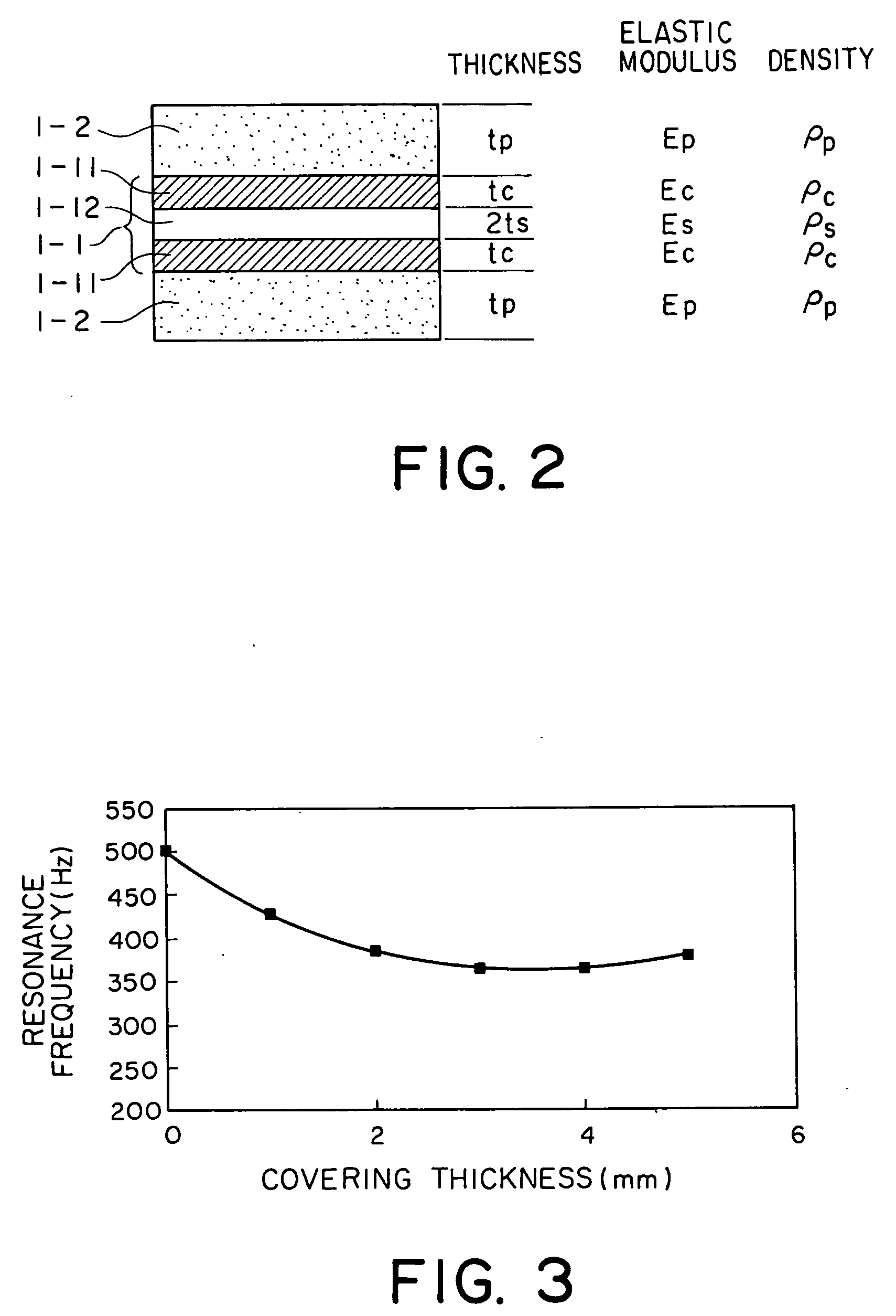
[0050] Preparation was made of a piezoelectric bimorph element having a rectangular shape and comprising two piezoelectric ceramics sheets (manufactured by NEC Tokin under the trade name of NEPEC10®) having the length of 32 mm, the width of 8 mm, and the thickness of 0.15 mm and a shim plate of brass having the length and the width equal to those of the piezoelectric ceramics sheets and the thickness of 50 μm. The piezoelectric bimorph element has a structure in which the shim plate is adhered between the two piezoelectric ceramics sheets by the use of an epoxy adhesive. Hereinafter, the above-mentioned structure will be called a single-plate structure.
[0051] On the other hand, as illustrated in FIG. 4, another piezoelectric bimorph element was produced in the following manner. Preparation was made of two sets of laminated piezoelectric ceramics members 5-1. Each of the laminated piezoelectric ceramics members 5-1 compris...
second embodiment
[Piezoelectric Bimorph Element of a Circular Shape]
[0058] Preparation was made of a piezoelectric bimorph element having a circular shape and comprising two piezoelectric ceramics sheets (manufactured by NEC Tokin under the trade name of NEPEC10®) having the diameter of 30 mm and the thickness of 0.15 mm and a shim plate of brass having the diameter equal to that of the piezoelectric ceramics sheets and the thickness of 50 μm. The piezoelectric bimorph element has a structure in which the shim plate is adhered between the two piezoelectric ceramics sheets by the use of an epoxy adhesive. Hereinafter, the above-mentioned structure will be called a single-plate structure.
[0059] By the use of piezoelectric ceramics sheets made of a material same as the above-mentioned piezoelectric ceramics sheets and having the same diameter and the thickness of 50 μm, a circular piezoelectric bimorph element of a laminated structure was prepared in the manner similar to that described in conjunctio...
third embodiment
[0066] [Covering member with V-shaped Grooves on Its Surface]
[0067] The acoustic vibration generating element experimentally prepared in the first embodiment was subjected to mechanical machining to form a plurality of V-shaped grooves on two principal surfaces of the covering member of the flexible material (silicone rubber in the embodiment). Each of the V-shaped grooves has a depth of 0.6 mm and extends in a direction perpendicular to a lengthwise direction. Thus, an acoustic vibration generating element according to a third embodiment of this invention was produced.
[0068]FIG. 7 shows the acoustic vibration generating element according to the third embodiment. The piezoelectric bimorph element 1-1 is covered with the covering member 1-2′. The covering member 1-2′ is provided with a plurality of V-shaped grooves 6-1 on its two principal surfaces.
[0069] The acoustic vibration generating element illustrated in FIG. 7 was subjected to measurement using the artificial internal ear i...
PUM
 Abstract
Description
Claims
Application Information