Turbine blade tip with optimized abrasive

a turbine blade and abrasive technology, applied in the direction of machines/engines, mechanical equipment, liquid fuel engines, etc., can solve the problems of insufficient blade tip clearance control system and unacceptable blade tip wear, so as to improve engine efficiency, improve blade tip clearance control, and prevent thermal degradation of abrasives

Inactive Publication Date: 2005-06-16
SIEMENS ENERGY INC
View PDF10 Cites 56 Cited by
  • Summary
  • Abstract
  • Description
  • Claims
  • Application Information

AI Technical Summary

Benefits of technology

[0007] It is an object of the invention to provide improved blade tip clearance control, and thus increased engine efficiency, by maintaining abrasion characteristics of an abrasive tipped blade while providing resistance to thermal degradation of the a

Problems solved by technology

However, operational experience has shown that the abradability of this blade tip clearance control system is insufficient.
While cBN abrasives exhibit excellent cutting ability when new, thermal decomposition of

Method used


Image

  • Turbine blade tip with optimized abrasive
  • Turbine blade tip with optimized abrasive

Examples


Embodiment Construction

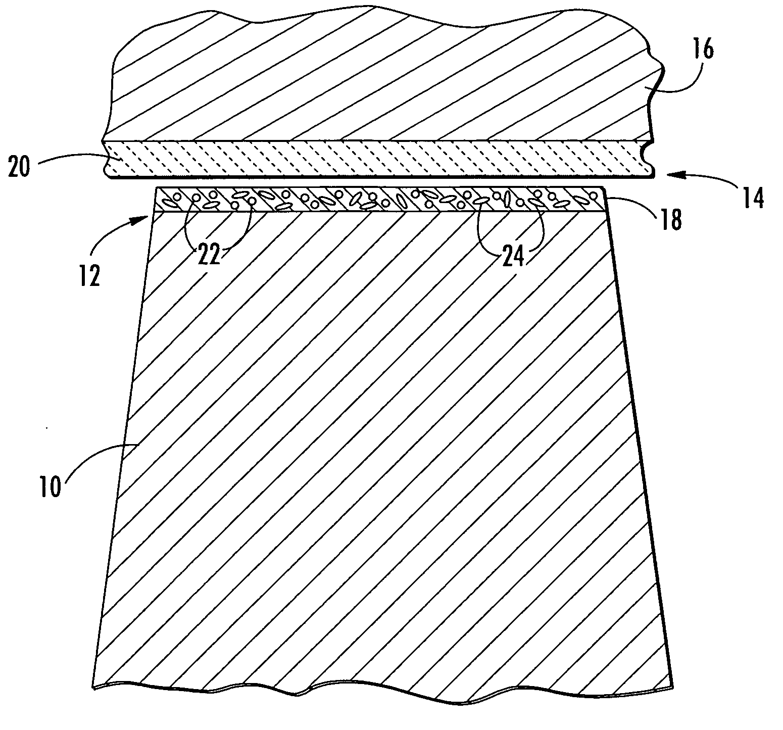
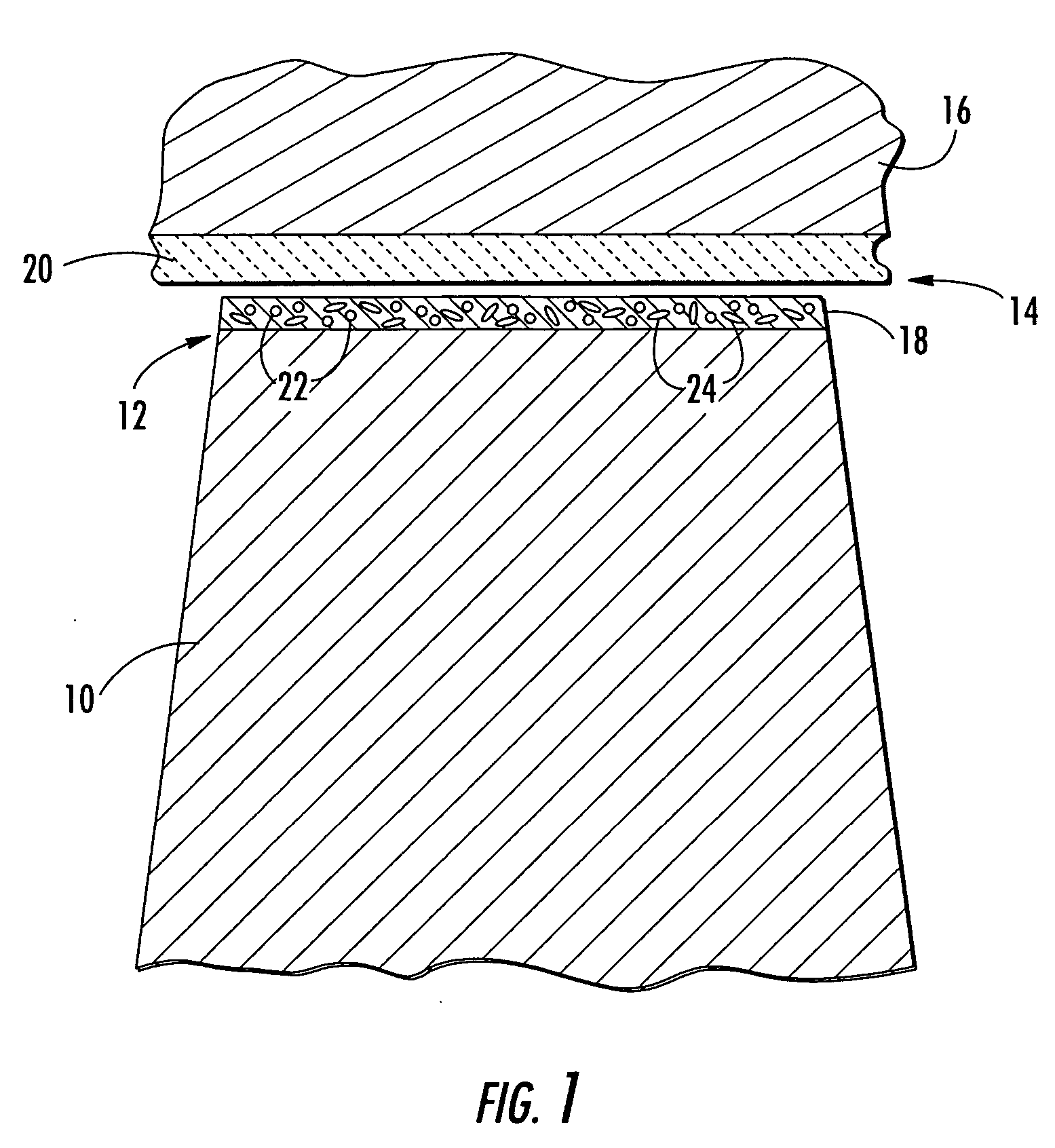
[0014] The invention is directed to an improved blade tip treatment to provide improved blade tip clearance control in the turbine section of an industrial gas turbine (IGT). While the embodiments disclosed are directed to abrasive clearance control between turbine blade tips and surrounding turbine ring segments, the coatings according to aspects of the invention can have application to other turbine components.

[0015] Referring to FIG. 1, a turbine blade 10 provides at its radially outer end a blade tip 12. The blade tip 12 is positioned relative to the radially inner surface 14 of a turbine ring segment 16 with as small a clearance as possible to minimize the leakage of the turbine hot gas flow past the blade tip 12, with the associated loss in turbine efficiency.

[0016] In an abrasion based tip clearance control system, the position of the blade tip 12 relative to the ring segment 16 is designed to allow abrasive contact between the blade tip 12 and the radially inner surface 14...


PUM

PropertyMeasurementUnit
Electrical resistanceaaaaaaaaaa
Abrasiveaaaaaaaaaa

Abstract

A new abrasive blade tip treatment is disclosed with the potential to provide improved blade tip clearance control in the turbine section of modern industrial gas turbines (IGT's). This blade tip treatment is composed of a unique combination of abrasive compounds that result in improved resistance to thermal degradation while retaining desirable initial cutting capacity.

Description

FIELD OF THE INVENTION [0001] This invention is directed generally to coatings for turbine blades, and more particularly to turbine blade tip coatings for tip clearance control. BACKGROUND OF THE INVENTION [0002] Typically, gas turbine engines are formed from a combustor positioned upstream from a turbine blade assembly. The turbine blade assembly is formed from a plurality of turbine blade stages coupled to discs that are capable of rotating about a longitudinal axis. Each turbine blade stage is formed from a plurality of blades extending radially about the circumference of the disc. Each stage is spaced apart from each other a sufficient distance to allow turbine vanes to be positioned between each stage. The turbine vanes are typically coupled to the shroud and remain stationary during operation of the turbine engine. [0003] The tips of the turbine blades are located in close proximity to an inner surface defined by ring segments. There typically exists a gap between each of the ...

Claims


Application Information

Patent Timeline
IPC IPC(8): C23C30/00C25D15/00F01D5/20
CPCC23C30/00F01D11/12C25D15/00
Inventor ALLEN, DAVID B.
Owner SIEMENS ENERGY INC
Why Eureka
Try Eureka