Male fertility assay method and device
a technology for assaying male fertility and assaying methods, applied in the field of assaying male fertility, can solve the problems of limiting the analysis of semen samples for couples who are failing to conceive, men are particularly unwilling to seek semen analysis, and women are reluctant to seek medical advi
- Summary
- Abstract
- Description
- Claims
- Application Information
AI Technical Summary
Benefits of technology
Problems solved by technology
Method used
Image
Examples
first embodiment
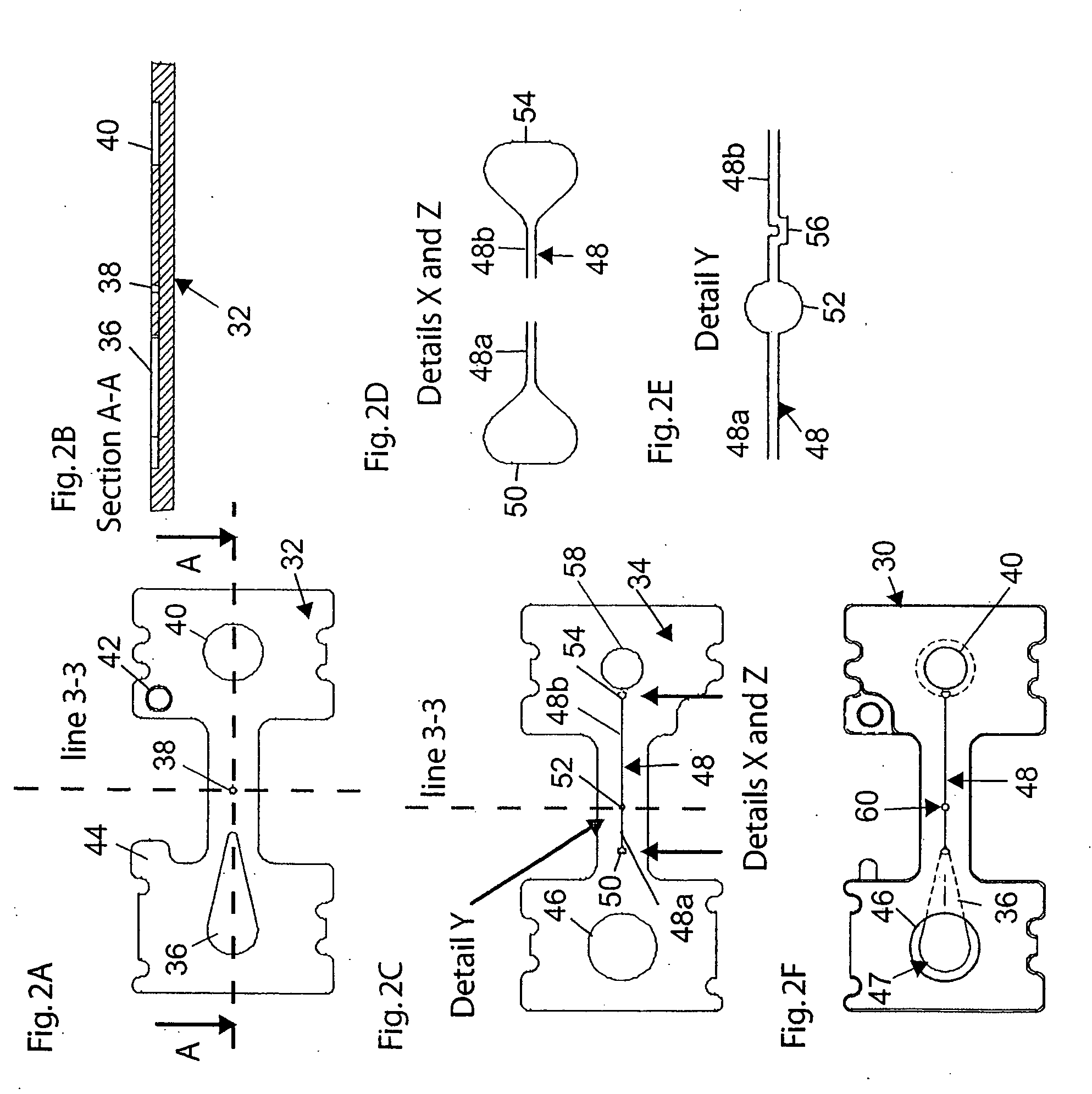
[0050] This section describes components of a collection reservoir device constructed in accordance with the invention. With reference to FIGS. 2A-2F, there is shown at FIG. 2F, a microfluidics structure 30 formed of a bottom plate 32 (FIG. 2A) bonded to an aligned top plate 34 (FIG. 2C) As seen best in FIGS. 2A and 2B, bottom plate 32 includes a tear-drop shaped recess 36 formed in its upper surface, at the upstream end region of the plate, a central cylindrical reservoir recess 38, which will form part of a collection reservoir in the structure, and a downstream recess 40. Also formed in the lower plate is a circular alignment recess 42 used in aligning the lower and upper plates when the two are bonded together, and a tab 44 used in aligning an optical element on structure 30, as will be seen.
[0051] Considering now the construction of top plate 34, and with reference to FIGS. 2C-2E, a sample-receiving opening 46 is formed at the upstream end of the plate. A microfluidics channel ...
second embodiment
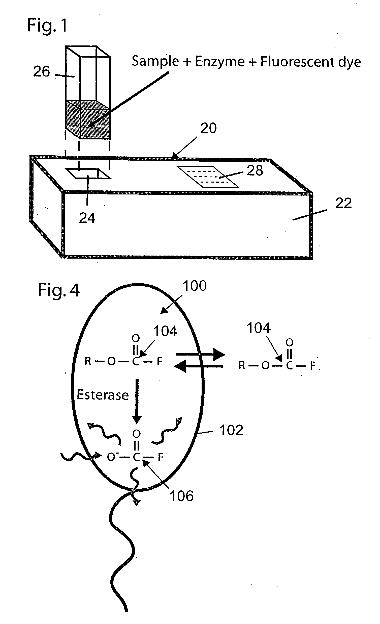
[0074] This section describes components of device constructed in accordance with the invention, in which sperm motility and density characteristics are measured by a pair of optical detectors positions at spaced apart location along a microfluidics channel. The device is illustrated in particular with respect to FIG. 1, which shows external housing features common to all three embodiments of the invention, FIG. 4, which illustrates fluorescence labeling of sperm cells, shows FIGS. 8A-8C, which illustrate microfluidic channel and optical-sensing components of the embodiment, FIG. 9, showing a flow diagram of the electronically controlled algorithm carried out by the device, and FIG. 12, which illustrates two exemplary output displays that are common to all three embodiments.
[0075]FIGS. 8A and 8B illustrate a portion of a microfluidics structure 140 in the second-embodiment device. Shown here are a sample-receiving reservoir 142, and an portion of a microchannel 144 whose upstream en...
third embodiment
[0093] 2. Either the graduated cylinder or a separate container with a smaller volume or diluted volume or semen mixed with other chemicals, compounds, or solvents is placed into the sample-receiving well of the device. The insertion of the sample holder is locked into place when it is snapped down into the well, the device electronics are activated, and a sharpened access port perforates the bottom of the sample holder giving the internal device fluid channel access to the semen sample. The semen sample flows into a dry loading reservoir or comes into immediate contact with a pre-filled fluid channel. Alternatively, the treated sample could be poured into the sample collection well after the microchannel is unsealed. In the first two embodiments described, sample pretreatment includes labeling the sample sperm with a fluorescence reporter. In the third embodiment, no sample labeling is required.
[0094] 3. If the prefilled fluid channel is kept separate from a dry loading reservoir, ...
PUM
| Property | Measurement | Unit |
|---|---|---|
| depth | aaaaa | aaaaa |
| width | aaaaa | aaaaa |
| depth | aaaaa | aaaaa |
Abstract
Description
Claims
Application Information
 - R&D
- Intellectual Property
- Life Sciences
- Materials
- Tech Scout
- Unparalleled Data Quality
- Higher Quality Content
- 60% Fewer Hallucinations
Browse by: Latest US Patents, China's latest patents, Technical Efficacy Thesaurus, Application Domain, Technology Topic, Popular Technical Reports.
© 2025 PatSnap. All rights reserved.Legal|Privacy policy|Modern Slavery Act Transparency Statement|Sitemap|About US| Contact US: help@patsnap.com


