Removable stent-graft

a stent and graft technology, applied in the field of stent grafts, can solve the problems of living tissue having a number of limitations and/or reactions, and no commercially available devices are designed to be removable,

Inactive Publication Date: 2005-06-16
WL GORE & ASSOC INC
View PDF46 Cites 110 Cited by
  • Summary
  • Abstract
  • Description
  • Claims
  • Application Information

AI Technical Summary

Benefits of technology

[0015] The present invention relates to removable, implantable devices such as removable stent-grafts or removable filter devices (e.g., embolic filters or vena cava filters). Such devices are intended for applications wherein it may be deemed necessary to remove the device at some time following implantation. Such applications may include stent-grafts for implantation in urethras, in biliary ducts, in the vascular system, the large or small intestine, or in the esophagus or trachea. It may be desirable for a stent-graft to be removable in applications w...

Problems solved by technology

All of these technologies exhibit a common disadvantage in that none of the commercially available devices are designed to be removable after implantation.
Even though great strides have been undertaken to enhance biocompatibility of these devices, it is still a synthetic, non-living tissue device that constitutes a foreign body.
As a result, living tissue has a number of limitations and/or reactions in coping with such a foreign body.
Typically, when a synthetic device becomes infected, or colonized by bacteria, there is little success in resolving such an infected device or infected area short of device removal from the patient.
In some instances, if an infected synthetic device cannot be removed enabling the antibiotic treatment of the effected living tissue, patient mortality can result due to septic shock.
Another issue associated with implantation of endoluminal...

Method used


Image

  • Removable stent-graft
  • Removable stent-graft
  • Removable stent-graft

Examples


example

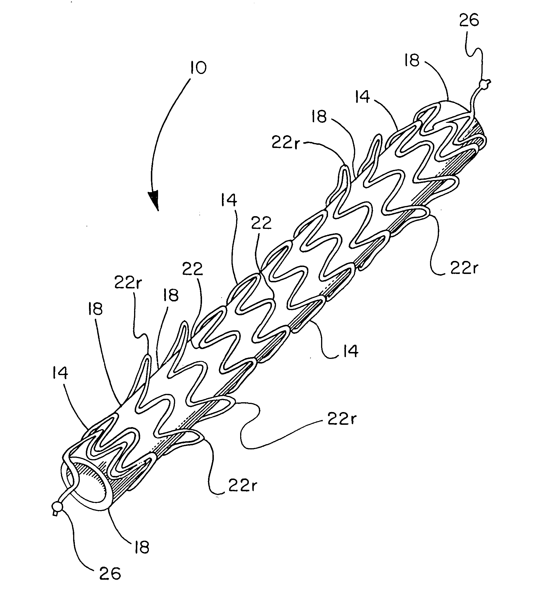
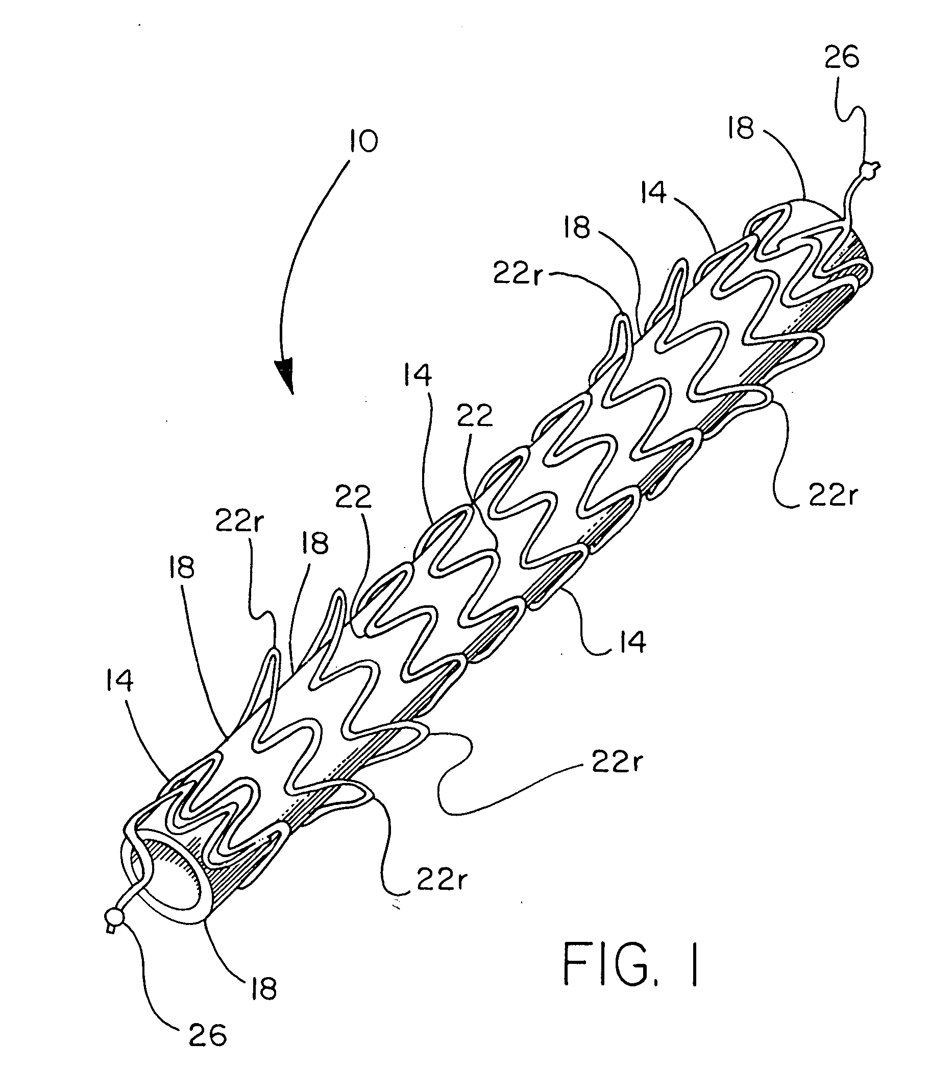
[0057] A stent component was produced by winding a 0.25 mm diameter nitinol wire (SMA Inc, Santa Clara Calif.) onto an 8 mm diameter wire forming fixture, creating a stent component as shown in FIG. 1. The wire-wound fixture was then subjected to heat treatment and quench cycles sufficient to set the wire into the desired form. FEP powder (Daikin America, Orangeburg N.Y.) was applied to the stent component by first stirring the powder into an airborne “cloud” in a standard kitchen-type blender and suspending the frame in the cloud until a uniform layer of powder was attached to the wire. The stent component was then subjected a thermal treatment of 320° C. for approximately one minute to cause the powder to melt and adhere as a coating over the stent component.

[0058] A sacrificial 7 mm inside diameter, 0.1 mm thick ePTFE tube that had been previously heated above 380° C., was pulled onto an 8 mm diameter mandrel, which involved slight stretching of the ePTFE tube. This tube was int...


PUM


Abstract

A removable device such as a stent-graft, intended for applications where it may be desirable to remove the device at some time following implantation. The stent-graft of the present invention includes a helically-wound stent component provided with a covering of graft material. It is removable by gripping an end of the helically-wound stent component with a retrieval device and applying tension to the stent component in the direction in which it is intended to be withdrawn from the site of implantation. The use of such a retrieval device allows the stent-graft to be removed remotely, such as via a catheter inserted into the body at a different location from the implantation site. The design of the stent-graft is such that the stent component is extended axially while the adjacent portion of the graft separates between windings of the stent component. The axial extension of the stent component, with portions of the graft still joined to the stent component, allows the device to be “unraveled” (or “unwound”) and removed through a catheter of diameter adequately small to be inserted into the body cavity that contained the stent-graft. It is removed atraumatically, without incurring significant trauma to the body conduit in which it had been deployed.

Description

FIELD OF THE INVENTION [0001] The present invention relates to the field of removable stent-grafts. BACKGROUND OF THE INVENTION [0002] Endoluminal stenting has provided a major advancement in clinical treatment modalities offering a significant reduction in perioperative treatment times, iatrogenic injury, postoperative morbidity and healing times. Even with the unprecedented clinical advantages of these devices, there still remains a number of limitations and disadvantages of the technologies currently available. The two primary technologies available for endoluminal stenting are the use of bare metal stents and stent devices provided with a covering or lining of a tubular graft material, i.e., stent-grafts. Either of these technologies may be made to be deployed via inflation of a catheter balloon (e.g., stainless steel stents) or to be self-expanding (e.g., nitinol stents). All of these technologies exhibit a common disadvantage in that none of the commercially available devices ...

Claims


Application Information

Patent Timeline
IPC IPC(8): A61F2/00A61F2/88
CPCA61B2017/22035A61F2/07A61F2/848A61F2/88A61F2220/005A61F2002/9528A61F2250/0071A61F2/89A61F2002/075A61F2002/072
Inventor CULLY, EDWARD H.HUTCHINSON, ERIN B.VONESH, MICHAEL J.WATSON, WOODROW W.
Owner WL GORE & ASSOC INC
Why Eureka
Try Eureka