Procedures for rapid build and improved surface characteristics in layered manufacture

Inactive Publication Date: 2005-06-16
JAMALABAD VIKRAM +2
View PDF42 Cites 35 Cited by
  • Summary
  • Abstract
  • Description
  • Claims
  • Application Information

AI Technical Summary

Benefits of technology

[0016] In the manufacturing phase, the part can be built up, bottom to top, by depositing the secondary and main materials, layer by layer. If secondary material is called for in the current layer, a secondary material nozzle can deposit a bead of secondary material of the desired bead width along the previously calculated path. A main material nozzle can then deposit a bead of main material of the desired bead width and along the previously calculated tool path. The flowable main material, formed along the previously formed secondary mold layers, can

Problems solved by technology

In particular, where the stacked bonded layers form the manufactured part side surfaces, the concavities can form sharp crevices having poor properties with respect to crack propaga

Method used


Image

  • Procedures for rapid build and improved surface characteristics in layered manufacture
  • Procedures for rapid build and improved surface characteristics in layered manufacture
  • Procedures for rapid build and improved surface characteristics in layered manufacture

Examples


Example

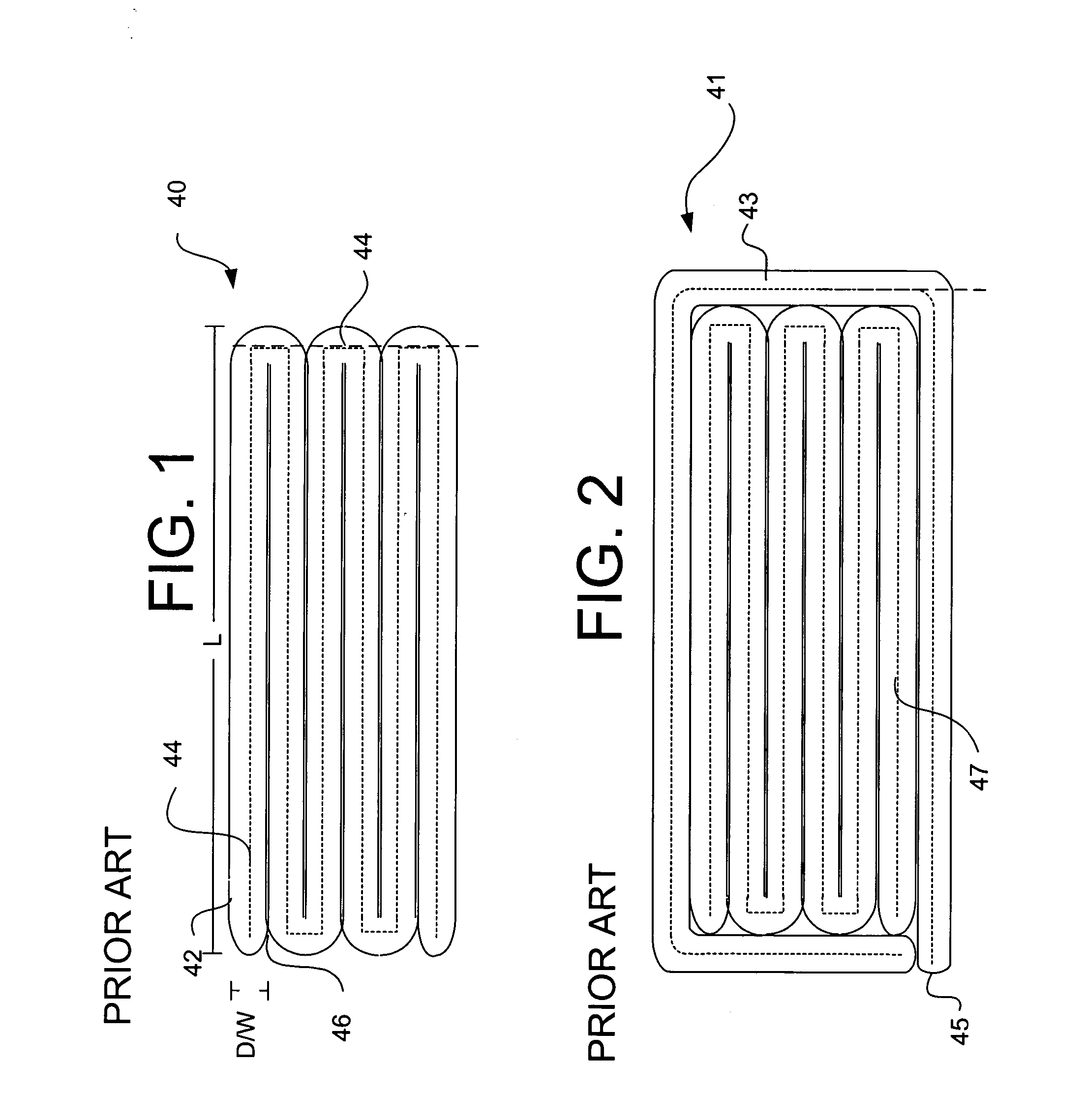
[0058]FIG. 1 illustrates a top view of a single layer of an object 40 made using layered manufacturing techniques. Object 40 is formed from a single bead 42 laid along a tool path 44, having a zigzag pattern to substantially fill a rectangular area. Bead 42 has a diameter or width indicated at D / W and a length indicated at L. Bead 42 may be seen to flow together at inter-bead region 46 where adjacent sections of the bead abut one another. Bead 42 and object 40 may be formed using any suitable manufacturing technique, for example, fused deposition techniques, multi-phase jet solidification techniques, or laser-engineered net shaping techniques. Bead 42 can be a ceramic suspension or slurry, a molten plastic, a powder-binder mixture, a polymeric material ready for curing or hardening, a molten metal, or other suitable materials which harden with time and / or exposure to an external stimulus. Bead 42 can also represent a curable strip of polymer or pre-polymer with polymerization initia...


PUM

PropertyMeasurementUnit
Timeaaaaaaaaaa
Structureaaaaaaaaaa
Electrical resistanceaaaaaaaaaa

Abstract

Methods for improving layered manufacturing techniques to improve an objects' surface properties and shorten manufacturing time for support structures. One aspect of the invention forms surfaces having reduced or no concavities between layers having improved crack resistance. One method deposits alternate, surface improvement material on each layer near the future location of the main material surface, followed by deposition of the main material, the edges of which conform to the previously deposited and solidified alternate material. In this method, the center of the main material layers can be concave rather than the interlayer regions. Another aspect of the invention provides removable structures to support the deposition of main material. The support structures provide support over main material cavities for depositing the material to form the cavity ceilings, while minimizing the time and material required to build the support structures. Minimized support structures include structures formed as columns supported by the cavity floor and angle braces to supported by the cavity walls. Some supports are supported by the side wall but not the floor, and other by the floor and not the side walls.

Description

RELATED APPLICATIONS [0001] The present application is related to co-pending U.S. patent application Ser. No. ______ [1100.1103101], titled TOOL PATH PLANING PROCESS FOR COMPONENT BY LAYERED MANUFACTURE, filed on date even herewith.FEDERAL SPONSORSHIP [0002] This invention was made with Government support under ______ contract number N00014-94-C-0115, entitled “______”. The Government has certain rights in the invention.FIELD OF THE INVENTION [0003] The present invention is related generally to machine manufacturing of components. In particular, the present invention is related to rapid prototyping manufacturing including layered manufacturing and solid freeform fabrication. BACKGROUND OF THE INVENTION [0004] Using conventional techniques, a desired article to be made can initially be drawn, either manually or automatically utilizing a computer-aided design (CAD) software package. The article can be formed by removing material from material stock to form the desired shape in a machi...

Claims


Application Information

Patent Timeline
IPC IPC(8): B29C67/00
CPCB29C64/40B29C64/118B29C64/106B28B3/10
Inventor JAMALABAD, VIKRAMGASDASKA, CHARLESORTIZ, MILTON
Owner JAMALABAD VIKRAM
Why Eureka
Try Eureka