Refractory armored quench ring

Inactive Publication Date: 2005-06-23
TEXACO INC +1
View PDF7 Cites 51 Cited by
  • Summary
  • Abstract
  • Description
  • Claims
  • Application Information

AI Technical Summary

Benefits of technology

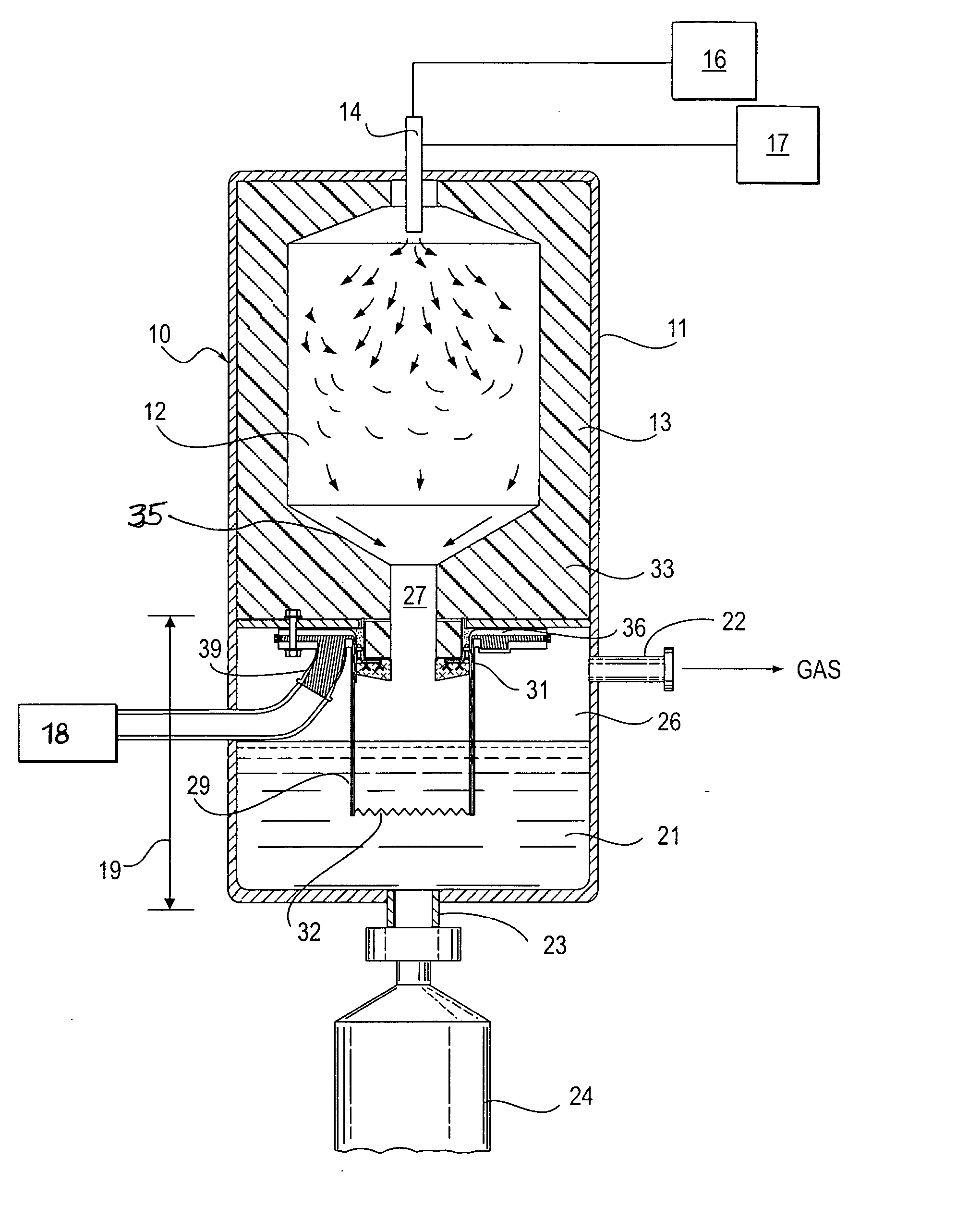
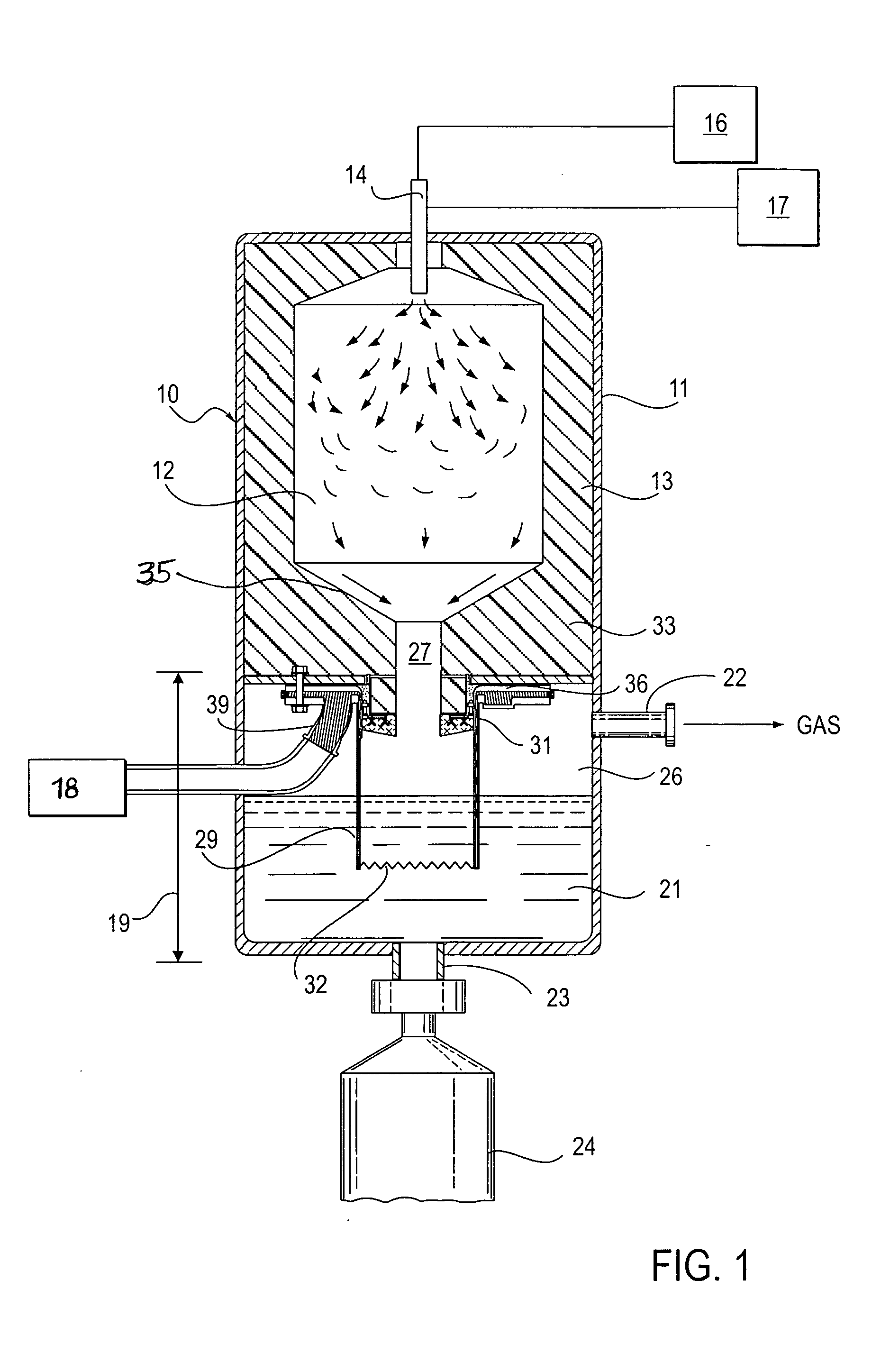
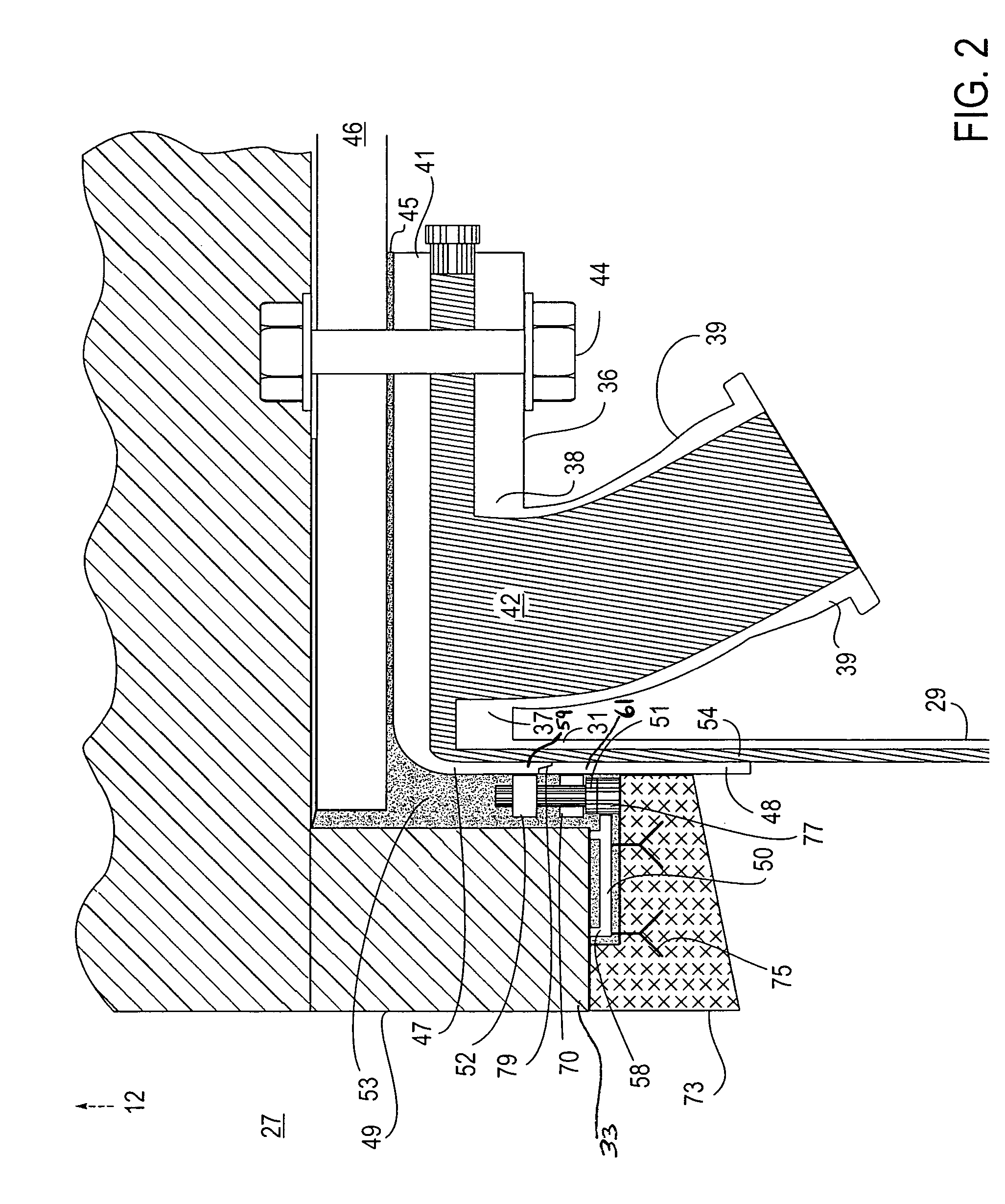
[0018] Toward overcoming the gasifier operating defects in gasifiers of the type noted, there is presently disclosed a gasifier quench ring which is provided with refractory layers that are located radially inward of the quench ring's normally exposed surfaces. The refractory layers protect the quench ring from exposure to the high temperature synthesis gas and slag exiting the reaction chamber bottom outlet. The quench ring is thereby insulated and physically protect

Problems solved by technology

The '423 patent, however, fails to protect the quench ring from the harsh thermal elements of the reactor.
Although a portion of the assembly is insulated, it does not provide an effective barrier which would avoid contact between the hot effluent stream and the cold quench ring surface.
There are several problems that are encountered due to the high temperature conditions within the gasifier.
Among those problems are the development of thermal stresses, which often result in damage to the quench ring as a result of the ring's close proximity to the hot effluent stream, and the lack of protection of the metal surfaces of the quench ring.
These problems are often manifested in the form of cracks and fissures which develop in parts of the quench ring.
One problem that may be experienced in gasifiers is the propensity of molten slag to harden and freeze in the gasifier's constricted throat.
This undesirable chilling action can, under particular circumstances, severely block the constricted throat opening, thereby precluding further operations.
Another problem with prior art quench ring and dip tube assembly arrangements includes the inability to repair or partially replace the quench ring while the gasifier is still fairly hot.
Repairing or replacing the quench ring when the entire gasifier has cooled down to approximately less than 100OF significantly delays resumption of the operation of the gasifier.
Yet another problem with the prior art quen

Method used


Image

  • Refractory armored quench ring
  • Refractory armored quench ring
  • Refractory armored quench ring

Examples


Embodiment Construction

[0037] Illustrative embodiments of the invention are described below. In the interest of clarity, not all features of an actual embodiment are described in this specification. It will, of course, be appreciated that in the development of any such actual embodiment, numerous implementation-specific decisions must be made to achieve the developers' specific goals, such as compliance with system-related and business-related constraints, which will vary from one implementation to another. Moreover, it will be appreciated that such a development effort might be complex and time-consuming, but would nevertheless be a routine undertaking for those of ordinary skill in the art having the benefit of this disclosure.

[0038] Referring to FIG. 1, in general, there is provided a gasifier or reactor vessel for gasifying a carbonaceous fuel mixture comprised of either solid, liquid or gaseous materials. The gasification process produces a hot effluent which comprises a synthesis gas, primarily com...


PUM


Abstract

An improved quench ring in combination with a reactor vessel having a refractory lined reaction chamber with a bottom outlet and a floor to support the refractory lined reaction chamber, wherein the quench ring is protected by a protective barrier comprising dense refractory brick, dense refractory ramming mix, refractory ceramic fiber, and a metal apron support. The protective barrier is removably attached to a portion of the quench ring hotface and protects the quench ring from the high temperature of the effluent exiting the reaction chamber.

Description

FIELD OF THE INVENTION [0001] The present invention is directed to an improved gasifier within which is a reactor that gasifiers carbonaceous fuel mixtures to produce a hot effluent comprising synthesis gas and residual slag. More specifically, this invention is directed to a support element that is located on the gasifier quench ring within the gasifier and that is used to protect the quench ring from the high temperatures of the hot effluent gas exiting through the reaction chamber floor. The support element protects the quench in such a manner that the quench ring is a refractory armored quench ring. BACKGROUND OF THE INVENTION [0002] In the production of synthesis gas by the partial oxidation of a carbonaceous fuel mixture, the process is conducted most effectively under high temperature and high pressure conditions. For example, for the production of synthesis gas from a carbonaceous fuel such as particulated coal, coke or even oil, a preferred operating temperature range of ab...

Claims


Application Information

Patent Timeline
IPC IPC(8): C10J3/00C10J3/48
CPCC10J3/485C10J3/845C10K1/101C10K1/08C10J2200/09
Inventor GROEN, JOHN CORWYN
Owner TEXACO INC
Why Eureka
Try Eureka