Method and apparatus to generate an RF excitation consistent with a desired excitation profile using a transmit coil array

a transmit coil array and excitation profile technology, applied in the field of mr imaging, can solve the problems of affecting the application of multi-dimensional excitation on scanners with general-purpose gradients, difficulty in controlling excitation profiles, etc., and achieve the effect of improving the management of multi-dimensional pulse length

Active Publication Date: 2005-06-23
GENERAL ELECTRIC CO
View PDF8 Cites 29 Cited by
  • Summary
  • Abstract
  • Description
  • Claims
  • Application Information

AI Technical Summary

Benefits of technology

[0010] The present invention is directed to the acceleration of a multi-dimensional excitation through the orchestrated driving of multiple transmit coils. The present invention emphasizes the coordination of multiple transmit elements to effect appropriate B1 spatiotemporal variations in a composite B1 field in order to improve the management of multi-dimensional pulse length while facilitating faithful production of desired excitation profiles. The present invention is also directed to the design of parallel excitation pulses with spatial and spatial-frequency domain weighting.

Problems solved by technology

Notwithstanding the advantages achieved by these pulse design tools, technical difficulties remain.
Issues with excitation pulse duration, excitation profile accuracy, and RF power absorption (SAR) represent some of the outstanding challenges in a variety of applications.
This limitation hinders applications of multi-dimensional excitation on scanners with general-purpose gradients.
Substantial subject-dependency of B1 field, resulting from increased wave behavior and source-subject interaction at high frequencies, may also contribute to the difficulty of excitation profile control.
This approach is limited as its application has been limited to certain profiles and tends to involve high RF power.
At high frequencies however, the capability of a field optimization approach is limited.
Even with calibration-guided adjustment of driving port weights, the degree to which the spatial variation of the composite B1 field approaches a desired level is highly dependent on the characteristics of component B1 fields, and results tend to be subject to considerable residual inhomogeneity.
Notwithstanding the excitation pulse length reduction achieved with a parallel excitation structure, application of such a structure has shown that particulars of the transmit elements are not fully taken into account.
That is, these known parallel transmit architectures fail to consider mutual coupling between transmit elements and are often dependent upon a simplistic transmit array geometry.
As such, spatial variations created by the transmit elements are not fully exploited.

Method used


Image

  • Method and apparatus to generate an RF excitation consistent with a desired excitation profile using a transmit coil array
  • Method and apparatus to generate an RF excitation consistent with a desired excitation profile using a transmit coil array
  • Method and apparatus to generate an RF excitation consistent with a desired excitation profile using a transmit coil array

Examples


Embodiment Construction

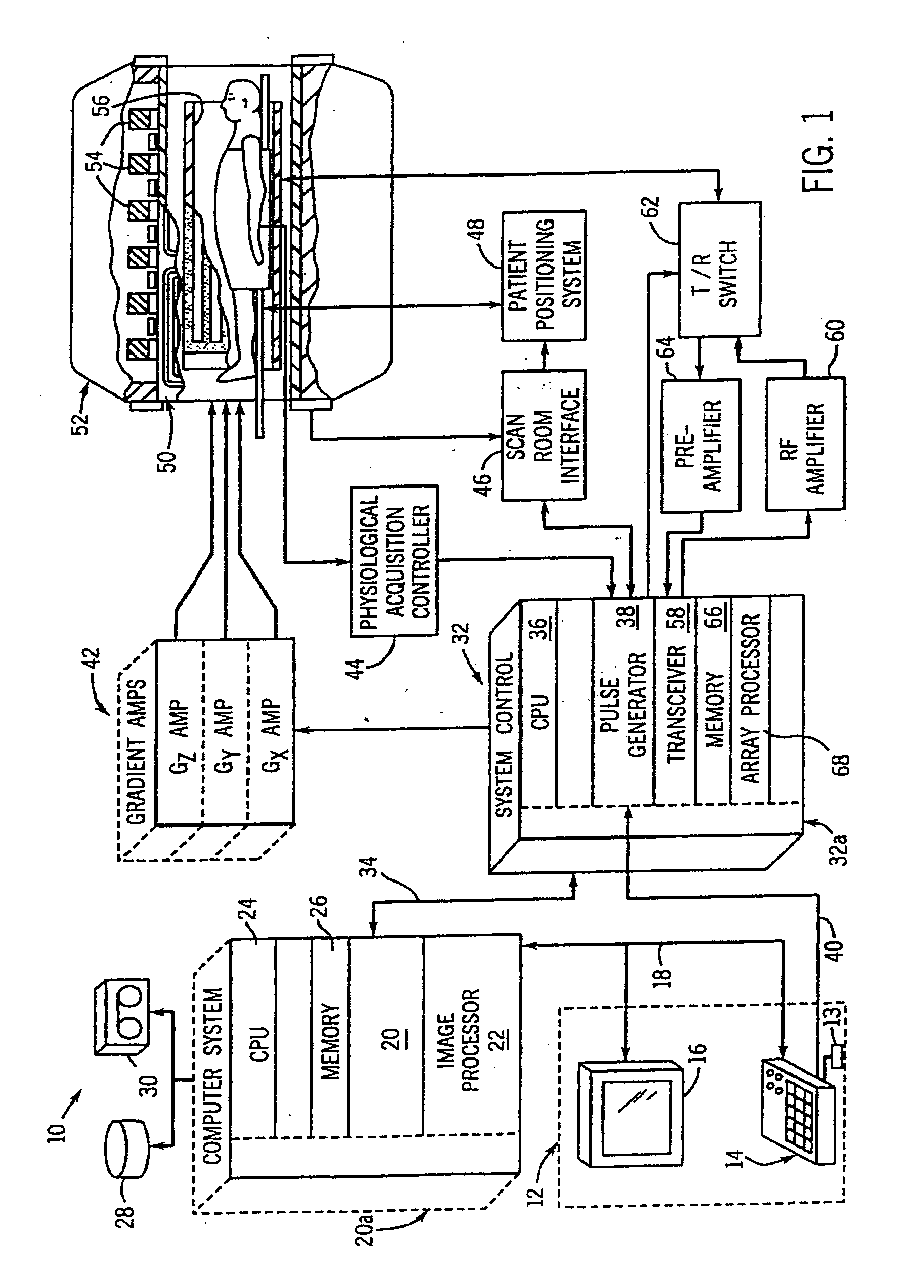
[0029] Referring to FIG. 1, the major components of a preferred magnetic resonance imaging (MRI) system 10 incorporating the present invention are shown. The operation of the system is controlled from an operator console 12 which includes a keyboard or other input device 13, a control panel 14, and a display screen 16. The console 12 communicates through a link 18 with a separate computer system 20 that enables an operator to control the production and display of images on the display screen 16. The computer system 20 includes a number of modules which communicate with each other through a backplane 20a. These include an image processor module 22, a CPU module 24 and a memory module 26, known in the art as a frame buffer for storing image data arrays. The computer system 20 is linked to disk storage 28 and tape drive 30 for storage of image data and programs, and communicates with a separate system control 32 through a high speed serial link 34. The input device 13 can include a mou...


PUM


Abstract

A system composed of multiple transmit coils with corresponding RF pulse synthesizers and amplifiers is disclosed. A method of designing RF pulses specific to each transmit coil to induce spatiotemporal variations in a composite B1 field is also disclosed. The present invention supports faithful production of desired excitation profiles and accommodates the use of any coil array geometry. The present invention also supports reduction in excitation pulse length. Through effective B1 field maps for each transmit coil, mutual coupling and other inter-coil correlations are accounted for in the RF pulse design.

Description

BACKGROUND OF THE INVENTION [0001] The present invention relates generally to MR imaging and, more particularly, to a method and apparatus of parallel excitation by a transmit coil array to realize a desired excitation profile. The present invention further relates to a parallel excitation pulse design method that accounts for mutual coupling between coils of the coil array and applies to any coil geometry. The present invention is further directed to targeted RF excitation across an imaging volume to accelerate MR imaging. [0002] When a substance such as human tissue is subjected to a uniform magnetic field (polarizing field B0), the individual magnetic moments of the spins in the tissue attempt to align with this polarizing field, but precess about it in random order at their characteristic Larmor frequency. If the substance, or tissue, is subjected to a magnetic field (excitation field B1) which is in the x-y plane and which is near the Larmor frequency, the net aligned moment, o...

Claims


Application Information

Patent Timeline
Patent Type & Authority Applications(United States)
IPC IPC(8): A61B5/055G01R33/36G01R33/3415G01R33/48G01R33/561
CPCG01R33/288G01R33/5612G01R33/561
Inventor ZHU, YUDONG
Owner GENERAL ELECTRIC CO
Why Eureka
Try Eureka