Clock signal distribution with reduced parasitic loading effects

a clock signal and parasitic loading technology, applied in the direction of generating/distributing signals, pulse automatic control, electrical equipment, etc., can solve the problems of power loss and effect, load effect, jitter, etc., and achieve the effect of reducing parasitic loading

a clock signal and parasitic loading technology, applied in the direction of generating/distributing signals, pulse automatic control, electrical equipment, etc., can solve the problems of power loss and effect, load effect, jitter, etc., and achieve the effect of reducing parasitic loading

US20050134337A1Active Publication Date: 2005-06-23MICRON TECH INC

Image

  • Clock signal distribution with reduced parasitic loading effects
  • Clock signal distribution with reduced parasitic loading effects
  • Clock signal distribution with reduced parasitic loading effects

Examples


Embodiment Construction

[0014] The invention is directed to reducing parasitic loading effects in clock signal distribution systems.

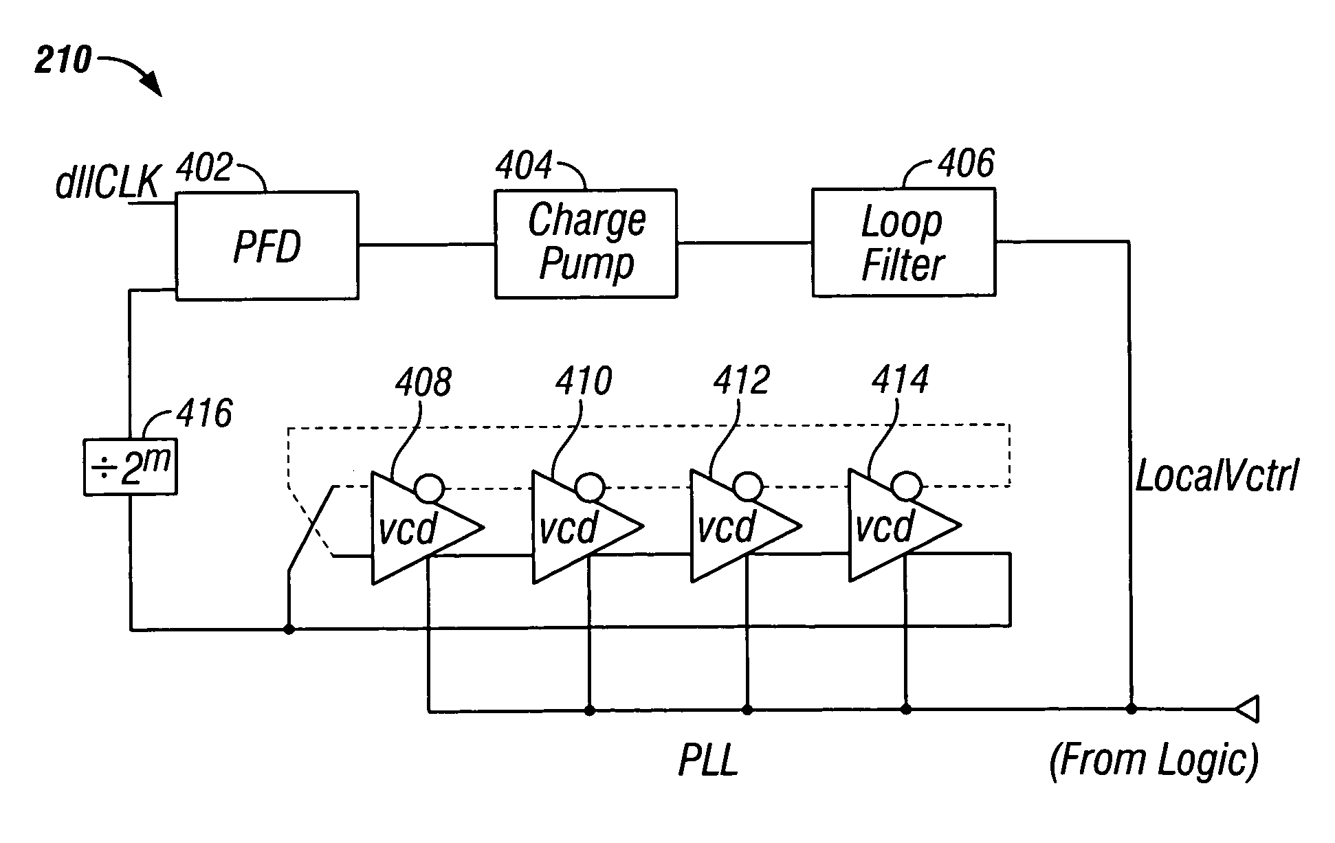
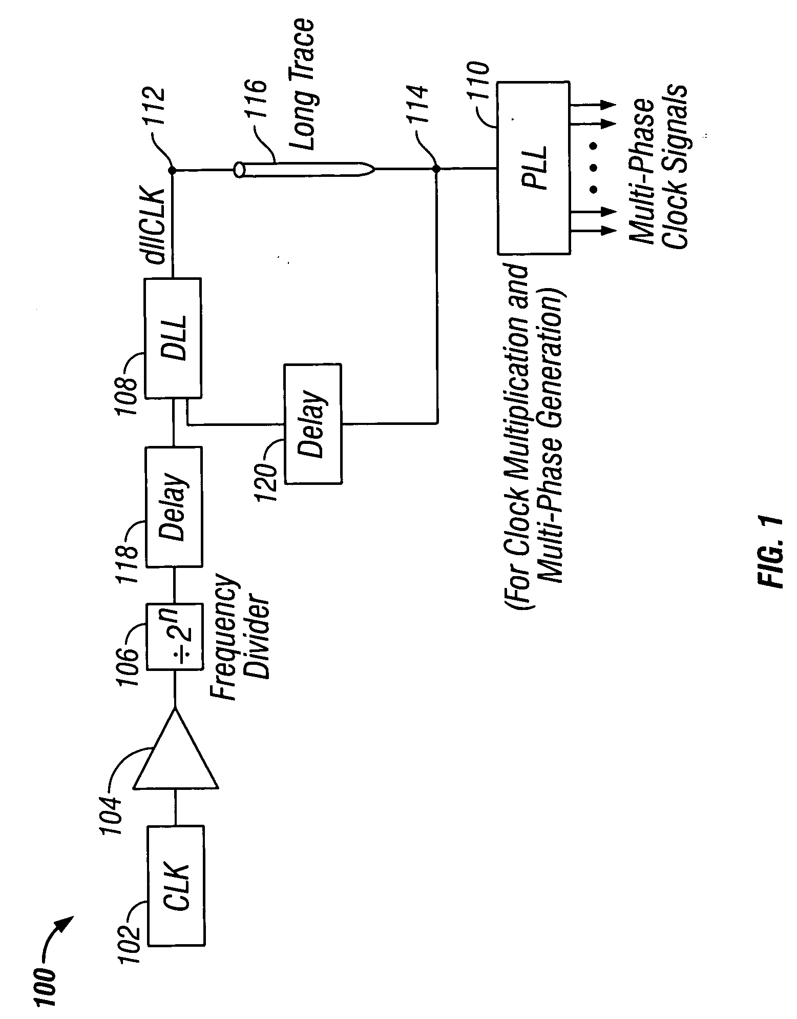
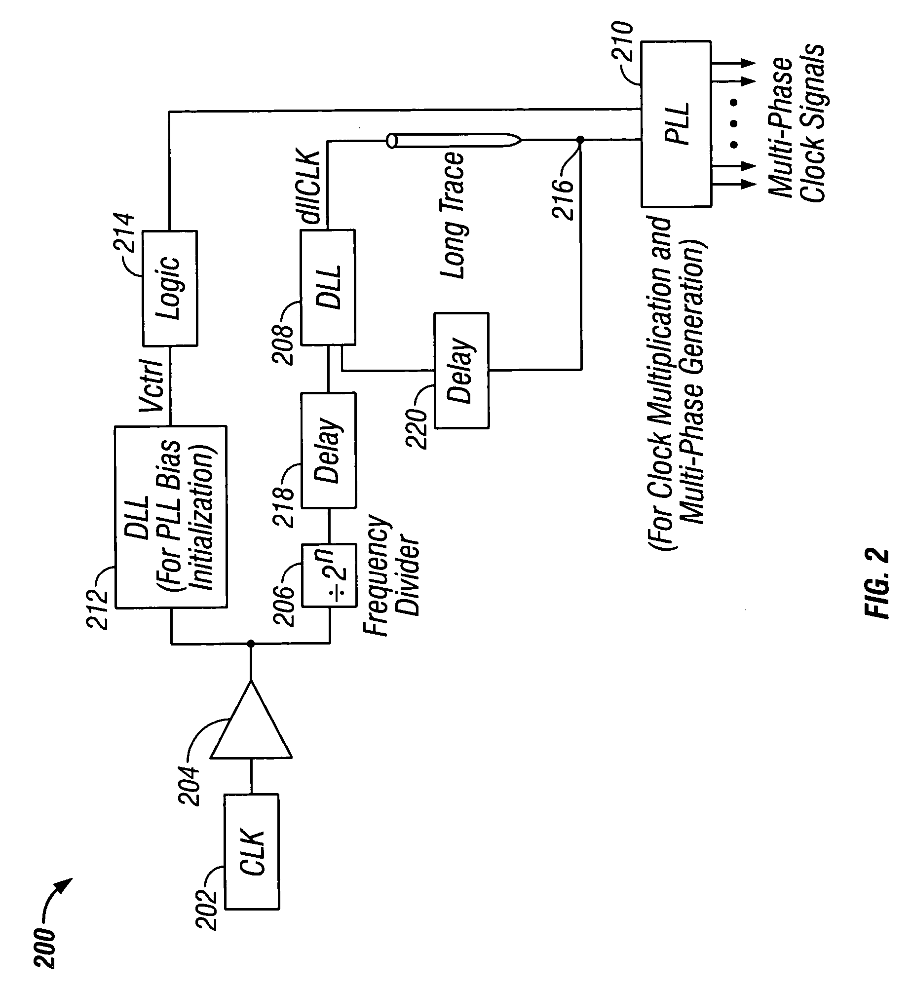
[0015]FIG. 1 shows a clock signal distribution system 100 in accordance with the invention. System 100 includes clock generator 102, buffer 104, frequency divider 106, delay-locked loop (DLL) 108 and phase-locked loop (PLL) 110. Clock generator 102 outputs a reference clock signal having a first frequency (fref) to buffer 104. Frequency divider 106 receives the reference clock signal from buffer 104, and outputs to DLL 108 a second clock signal having a frequency (f2) that is equal to the reference clock frequency divided by 2n (i.e., f2=fref / 2n) for all positive integers n. DLL 108“locks” to the second clock signal and outputs at output 112 a third clock signal preferably having the same frequency (f2) as the second clock signal. Other frequencies may of course be provided by DLL 108. “Locking” by DLL and PLL circuits is described in greater detail below in connection with F...


PUM


Abstract

Clock signal distribution systems with reduced parasitic loading effects are provided. A reference clock is frequency-divided to produce a lower frequency clock signal. A delay-locked loop (DLL) circuit locks to the lower frequency clock signal, and outputs a corresponding lower frequency clock signal for distribution over a long trace. Power consumption caused by parasitic capacitance of the trace is thereby reduced. Parasitic effects associated with clock jitter are also reduced. A frequency multiplying phase-locked loop (PLL) circuit locks to the lower frequency clock signal, and outputs at least one clock signal having a higher frequency than the lower frequency signal.

Description

BACKGROUND OF THE INVENTION [0001] This invention relates to clock signal distribution systems. More particularly, this invention relates to clock signal distribution systems with reduced parasitic loading effects. [0002] System clock signals are typically remotely generated for distribution to various digital circuit subsystems. The system clock generator and the digital subsystems may be located in geographically disparate regions of the digital circuit. Clock signals are distributed throughout the digital circuit over traces (i.e., device interconnects; e.g., a signal wire) having characteristic parasitic capacitances. The parasitic capacitances result in loading effects (e.g., power loss and effects associated with clock jitter) that can vary in direct proportion to both clock frequency and trace length. Technology trends indicate that the physical separation of system clock generators and associated digital sub-systems will increase as digital circuits become progressively more...

Claims


Application Information

Patent Timeline
23 Jun 2005
Publication
US20050134337A1
IPC
G06F1/10; H03L7/06; H03L7/07; H03L7/081; H03L7/099
CPC
G06F1/10; H03L7/0995; H03L7/0812; H03L7/07; H03L7/0816
Inventors
LEE, SEONG-HOON; LIN, FENG