Superconductivity magnet apparatus

a superconductivity magnet and magnet technology, applied in the direction of superconducting magnets/coils, magnetic bodies, instruments, etc., can solve the problem of axis-unsymmetrical error magnetic field, error magnetic field, and inability to place samples perpendicularly to the main magnetic field, so as to suppress the generation of axis-unsymmetrical magnetic field and uniform magnetic field

Inactive Publication Date: 2005-06-23
HITACHI LTD
View PDF2 Cites 18 Cited by
  • Summary
  • Abstract
  • Description
  • Claims
  • Application Information

AI Technical Summary

Benefits of technology

[0018] In the superconductivity magnet apparatus comprising a split-type electromagnet, an access port allowing an access to a measurement space by way of a gap between blocks of the split-type electromagnet inevitably causes a deficiency portion such as a cutout portion and an axis-unsymmetrical area. This axis-unsymmetrical area is constituted with a material having a relative magnetic permeability in the range 1.000 to 1.002 extremely close to that of the air. It is desirable to configure the constitution element of the area into an axis-symmetry. According to the present invention, erroneous generation of an axis-unsymmetrical magnetic field can be suppressed, and a uniform magnetic field can thus be generated without noticeably increasing the magnetic-field compensation power of an magnetic-field compensation means such as a magnetic-compensation coil.

Problems solved by technology

In the conventional NMR, however, the sample cannot be placed perpendicularly to the main magnetic field except for a special application such as a microprobe in which a solenoid-type antenna is wound directly around an extremely small test tube containing the sample.
However, even the magnetism of SUS316 or SUS316L, which is generally said to be non-magnetic, cannot be ignored in an NMR magnet, and the uniformity of the magnetic field deteriorates due to SUS bobbins.
However, in the case of a split-type magnet allowing the sample to be inserted from the side face of the magnet, due to a cutout of the bobbin for providing bore (through hole), an axis-unsymmetrical error magnetic field, namely an error magnetic field not symmetrical on the basis of an axis, is generated.
The NMR magnet cannot compensate the axis-unsymmetrical error magnetic field by merely designing the above main coil.
However, the magnitude of the error magnetic field caused by the non-symmetry of the magnet is generally greater than the magnitude of the error magnetic field caused by a manufacturing error of the magnet.

Method used


Image

  • Superconductivity magnet apparatus
  • Superconductivity magnet apparatus
  • Superconductivity magnet apparatus

Examples


first embodiment

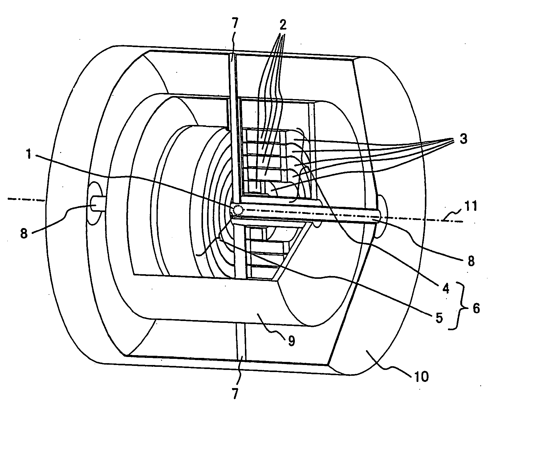
[0023] A first embodiment of the invention is shown in FIG. 1. A superconductivity wire is wound around coaxial multiple bobbins 3 to form coaxial multiple layer superconductivity coils 2. The first superconductivity-coil block 4 (hereafter it's abbreviated as the first block 4) is configured by forming the superconductivity coils 2 into such a coaxial multi-layer structure. The second superconductivity-coil block 5 (hereafter it's abbreviated as the second block 5) is placed so as to face the first block 4. The configuration of the second block 5 is the same as that of the first block 4. The first block 4 and the second block 5 are arranged in the state of facing mutually so that the axes of magnetic fields generated by their respective coils coincide on the direction, and there is a gap between the blocks 4 and 5. The direction of the axis 11 of the magnetic field is also the direction of the axis of each coil. A split-type electromagnet 6 is configured by joining the first block ...

second embodiment

[0034] In the case of the first embodiment, the entire bobbin including the support structure body 13 is made of a material having a relative magnetic permeability in the range 1.000 to 1.002. However young's modulus of the titan alloy used in the first embodiment is smaller than that of stainless steel. And fabrication and welding processes to titan are not easy. The high manganese steel used the first embodiment is difficult to obtain and to fabricate easily.

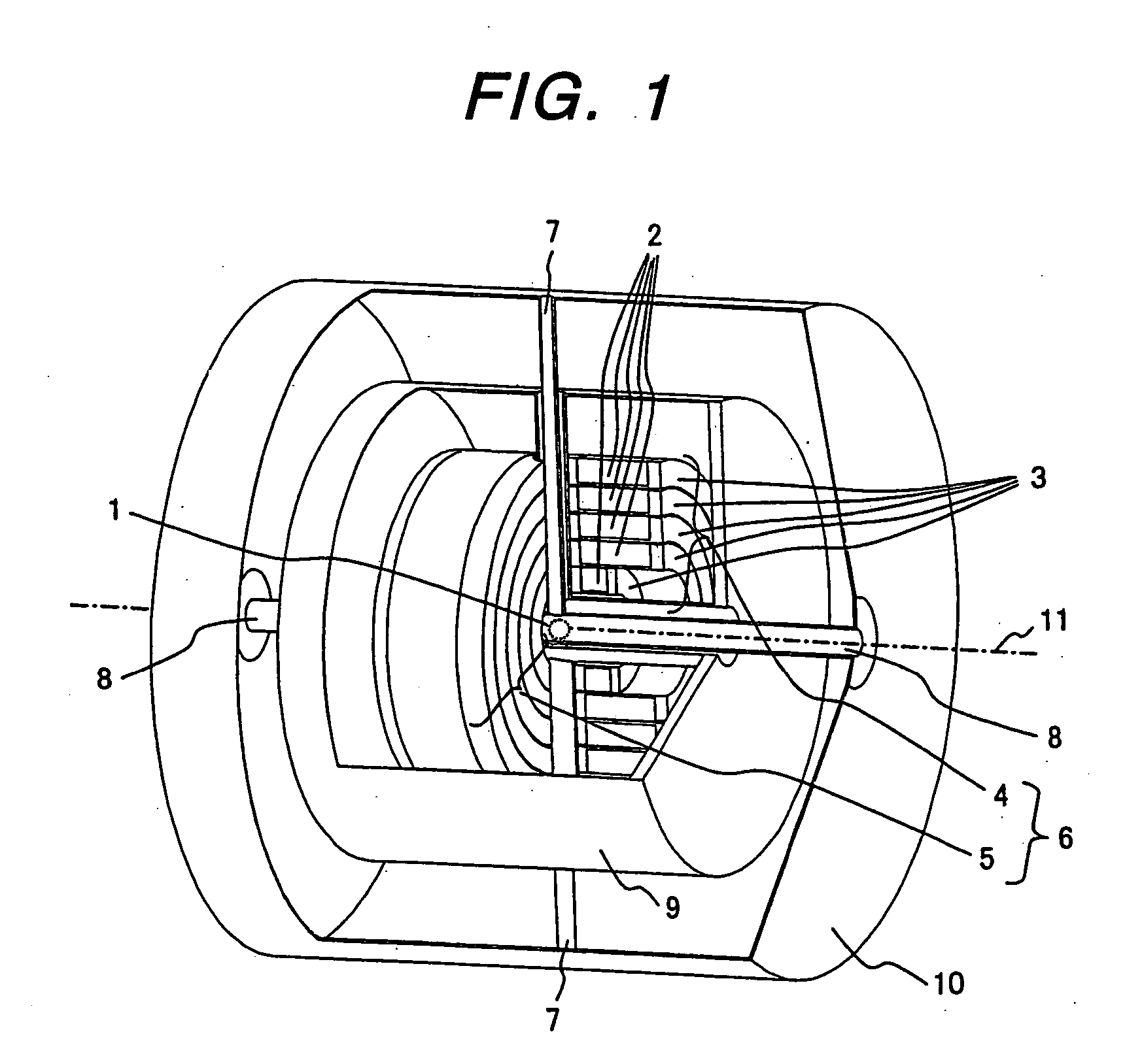
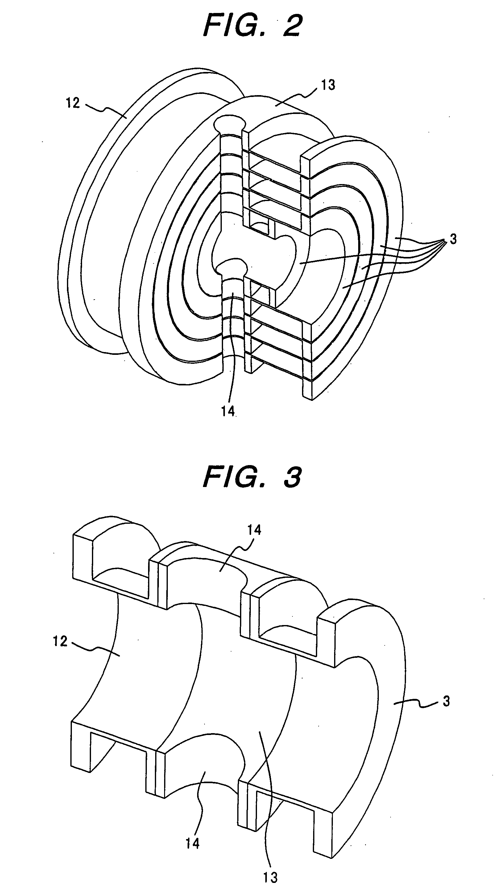
[0035] Considering above-mentioned matter, in the case of the second embodiment, the bobbins 3 and 12 and the support structure body 13 are made of different materials, and they are formed into a single assembly as shown in FIG. 3. To put it concretely, a stainless steel, i. e., SUS316 or SUS316L is used as material for the bobbins 3 and 12 requiring high durability and large Young's modulus. On the other hand, as material for the support structure body 13 including a cutout such as the through (penetrating) hole 14 of the fi...


PUM

PropertyMeasurementUnit
magnetic fieldaaaaaaaaaa
radiusaaaaaaaaaa
radiusaaaaaaaaaa

Abstract

The present invention provides a superconductivity magnet apparatus for generating a uniform magnetic field suitable for NMR applications. The superconductivity magnet apparatus has an access port for allowing an access to the center of the magnetic field from an external position separated away from the center in a direction other than the axial direction of a split-type superconductivity electromagnet employed in the magnet apparatus. In the superconductivity magnet apparatus, a gap exists between first and second superconductivity coil blocks facing each other to form the split-type superconductivity electromagnet. To put it in detail, the access port allows an access to a measurement space at the center of the magnet by way of the gap. A configuration element of the magnet such as a coil bobbin is cut out for providing the access port. An area including a deficiency portion caused by the cutout portion or the like is filled up with a material having a relative magnetic permeability in the range 1.000 to 1.002 as an axis-symmetrical area. By using the material with a relative magnetic permeability in the range 1.000 to 1.002, the strength of an erroneously generated magnetic field can be reduced so that a magnet producing a uniform magnetic field can be provided.

Description

FIELD OF THE INVENTION [0001] The present invention relates to a superconductivity magnet apparatus having a split-type electromagnet. The superconductivity magnet apparatus is suitable for an application to an NMR (Nuclear Magnetic Resonance) apparatus. BACKGROUND OF THE INVENTION [0002] In general, the magnet used for the NMR apparatus is constituted by a coaxial nest type multi-layer solenoid. The magnet is placed in such a state that the center axis of the magnet points to the vertical direction. A port for inserting a sample to be measured, which is a through hole in the vertical direction, is provided in the proximity of the center axis of the magnet. The sample is inserted into the port from a position on the upper side, and the probe enclosing an antenna (a detection coil) for detecting a signal is inserted into the port from a position on the lower side. [0003] The sensitivity of detection of an NMR signal varies in dependence on the shapes of the sample and the antenna as ...

Claims


Application Information

Patent Timeline
Patent Type & Authority Applications(United States)
IPC IPC(8): G01R33/3815H01F1/00H01F6/00H01F6/06
CPCH01F6/06H01F6/00
Inventor WAKUDA, TSUYOSHIMAKI, KOHJITSUCHIYA, MITSUYOSHIOKADA, MICHIYATSUKAMOTO, HIDEOKAJIURA, SOUJIKIDO, SHUICHI
Owner HITACHI LTD
Why Eureka
Try Eureka