Circular extinction contrast imaging microscope

a contrast imaging and microscope technology, applied in the field of optical microscopy systems and methods, can solve the problems of woefully under-utilized cd and or spectroscopy, the difficulty of measuring cd of organized media with commercial instruments is so extreme, and achieves the effect of improving the signal-to-noise ratio

Inactive Publication Date: 2005-06-23
UNIV OF WASHINGTON
View PDF3 Cites 26 Cited by
  • Summary
  • Abstract
  • Description
  • Claims
  • Application Information

AI Technical Summary

Benefits of technology

[0016] The imaging systems and methods of the present invention provide images that can be separated into true circular extinction that can be scaled by linear dichroism and linear birefringence by means of a single equation. Moreover, in the methods of the present invention, it is not required that a sample under investigation be rotated or aligned. Signal to noise ratio is improved by signal averaging, and in relating the measured intensities to an area within the image that is expected to have no circular extinction effects. This allows for the straightforward elucidation of the true CD spectrum for a sample that d

Problems solved by technology

Despite its widespread use in structure determination, CD and OR spectroscopy is woefully under-utilized, especially in the analysis of organized media that exhibit linear anisotropies.
Ever since OR was discovered in 1811 by Arago, measurements of chiroptical effects have been nearly impossible for anisotropic samples.
The difficulty of measuring CD of organized media with commercial instruments is so extreme that it is practically assumed from the start that CD measurement is a technique restricted to isotropic solutions.
Part of the problem stems from the fact that electronic modulators typically generate sinusoidally varying polarization states instead of rectangular waveforms, introducing a small admixture of linearly polarized light into their circularly polarized

Method used


Image

  • Circular extinction contrast imaging microscope
  • Circular extinction contrast imaging microscope
  • Circular extinction contrast imaging microscope

Examples


Embodiment Construction

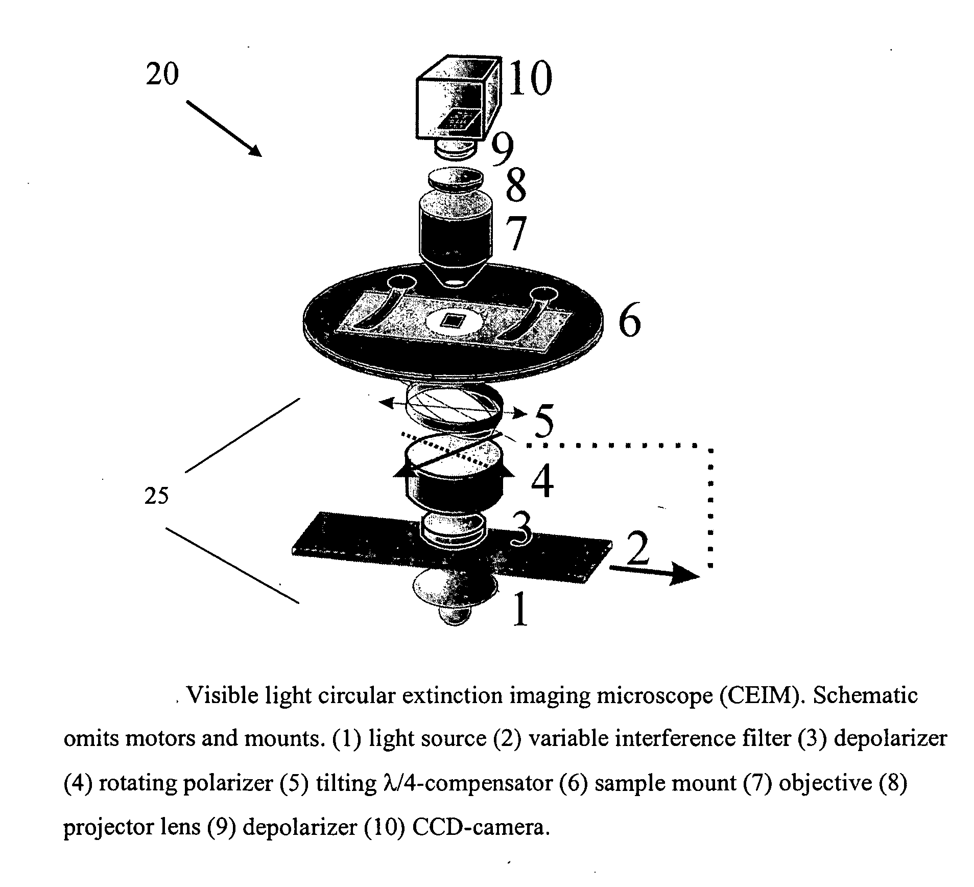
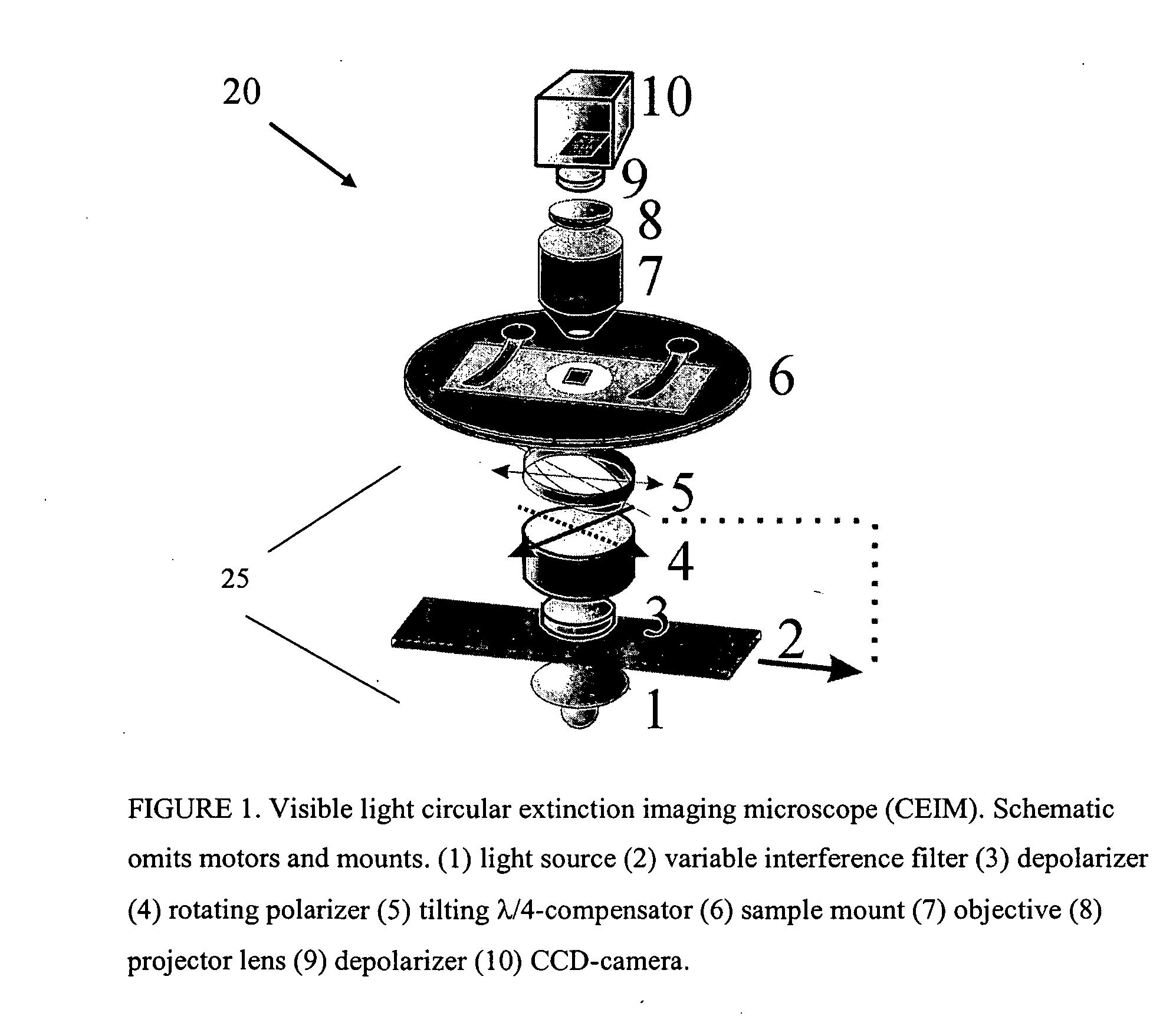
[0033] The present invention, in certain aspects, provides circular extinction contrast imaging techniques and microscopes based on the mechanical modulation of near perfect circularly polarized light (CPL) in conjunction with CCD detection. Signal to noise lost in slow modulation (e.g., less than about 30 Hz) can be regained by signal averaging techniques using CCD camera images. The systems and techniques of the present invention are particularly useful for studying chiro-optical effects—spontaneous perturbations of the state of electromagnetic radiation exerted by chiral molecules. Molecular chirality, as evidenced by changes in the polarization state of light passing through a given sample, is a shared characteristic of all biopolymers. Tissue sections or fixed cell samples, for example, routinely used in cell biological research and pathological procedures, are replete with optically active biopolymers.

[0034] A circular extinction imaging microscope (CEIM) according to one emb...


PUM


Abstract

Systems and methods for producing circular extinction (CE) contrast images of anisotropic samples. Microscope systems for determining circular extinction (CE), the differential transmission of left and right circularly polarized light resulting from circular dichroism (CD) of an anisotropic sample, include mechanically driven optical components and an image detector such as a monochromatic CCD camera to detect light intensities. In one aspect, optical components include a tunable filter, a rotatable linear polarizer and a variable retarder. The tunable filter is adjustable to provide light at a specific desired wavelength. The linear polarizer is adjustable to provide linearly polarized light with a specific wave vector, and the variable retarder is adjustable to produce near perfect circular polarized light at every selected wavelength. For example, in one aspect, the variable retarder includes a linear birefringent plate tiltable around one of its eigenmodes perpendicular to the wave vector of polarized light. The plate may be controllably tilted so that it functions as a perfect λ/4 plate at each wavelength.

Description

CROSS-REFERENCES TO RELATED APPLICATIONS [0001] This application is a non-provisional application of U.S. Provisional Application Ser. No. 60 / 512,628, filed Oct. 17, 2003, the contents of which are hereby incorporated by reference.STATEMENT AS TO RIGHTS TO INVENTIONS MADE UNDER FEDERALLY SPONSORED RESEARCH OR DEVELOPMENT [0002] The government may have certain rights to the invention based on NSF Grant No. CHE-0092617, “Optical Probes of Crystal Growth Mechanisms.”BACKGROUND OF THE INVENTION [0003] The present invention relates generally to optical microscopy systems and methods, and more particularly to systems and methods for producing circular extinction (CE) contrast images, including circular dichroism (CD) images. [0004] Circular dichroism (CD) is the differential absorption (circular extinction, CE) of left- and right-circularly polarized light (CPL) traversing a sample. CD reveals the dis-symmetry of a molecule's chromophores which then also exhibit circular birefringence (CB...

Claims


Application Information

Patent Timeline
IPC IPC(8): H04N5/225H04N5/235
CPCH04N5/2354H04N23/74
Inventor KAMINSKY, WERNERKAHR, BART
Owner UNIV OF WASHINGTON
Why Eureka
Try Eureka