Tape recording head

a recording head and magnetic tape technology, applied in the direction of recording on magnetic tapes, mounting heads within the housing, instruments, etc., can solve the problem of excessive wear on the surface of the transducer, and achieve the effect of sufficient wear resistance and high bandwidth fine actuation

Active Publication Date: 2005-06-23
META PLATFORMS INC
View PDF19 Cites 12 Cited by
  • Summary
  • Abstract
  • Description
  • Claims
  • Application Information

AI Technical Summary

Benefits of technology

[0010] In accordance with the principles of the present invention, there is disclosed a tape recording head comprising a support plate having a contoured surface with an opening in the contoured surface which allows head chips to protrude far enough to allow proper head tape contact for recording. An embodiment of the tape recording head comprising a support plate having a cylindrical surface with a rectangular opening in the cylindrical surface is described. The support plate is fixed on a coarse actuator so that the support plate and actuator move together in a direction perpendicular to the direction of tape motion over the head to position magnetic transducers on the head chips on data tracks recorded at positions across the tape width. The head chips comprising rowbar substrates containing a plurality of magnetic transducers are supported on a carrier mounted on a fine actuator. The head chips are not fixed to the support plate to allow low-mass, high bandwidth fine actuation capability of the magnetic transducers on the recorded data tracks. The tape flies over the support plate with a spacing of approximately 1-5 microns depending on the tape, tape speed and skirt radius. The support plate is made of ceramic material, such as Al—Ti—C, or a hardened metallic alloy to provide sufficient wear resistance at the edges of the tape and near the support plate opening where contact with the tape may occur.

Problems solved by technology

However, the development of small footprint, higher performance tape drive systems has created various problems in the design of a tape head assembly for use in such systems.
However, the contour of the head must be such that the pressure exerted by the tape on the transducer is not so high that the surface of the transducer wears excessively.

Method used


Image

  • Tape recording head
  • Tape recording head
  • Tape recording head

Examples


Embodiment Construction

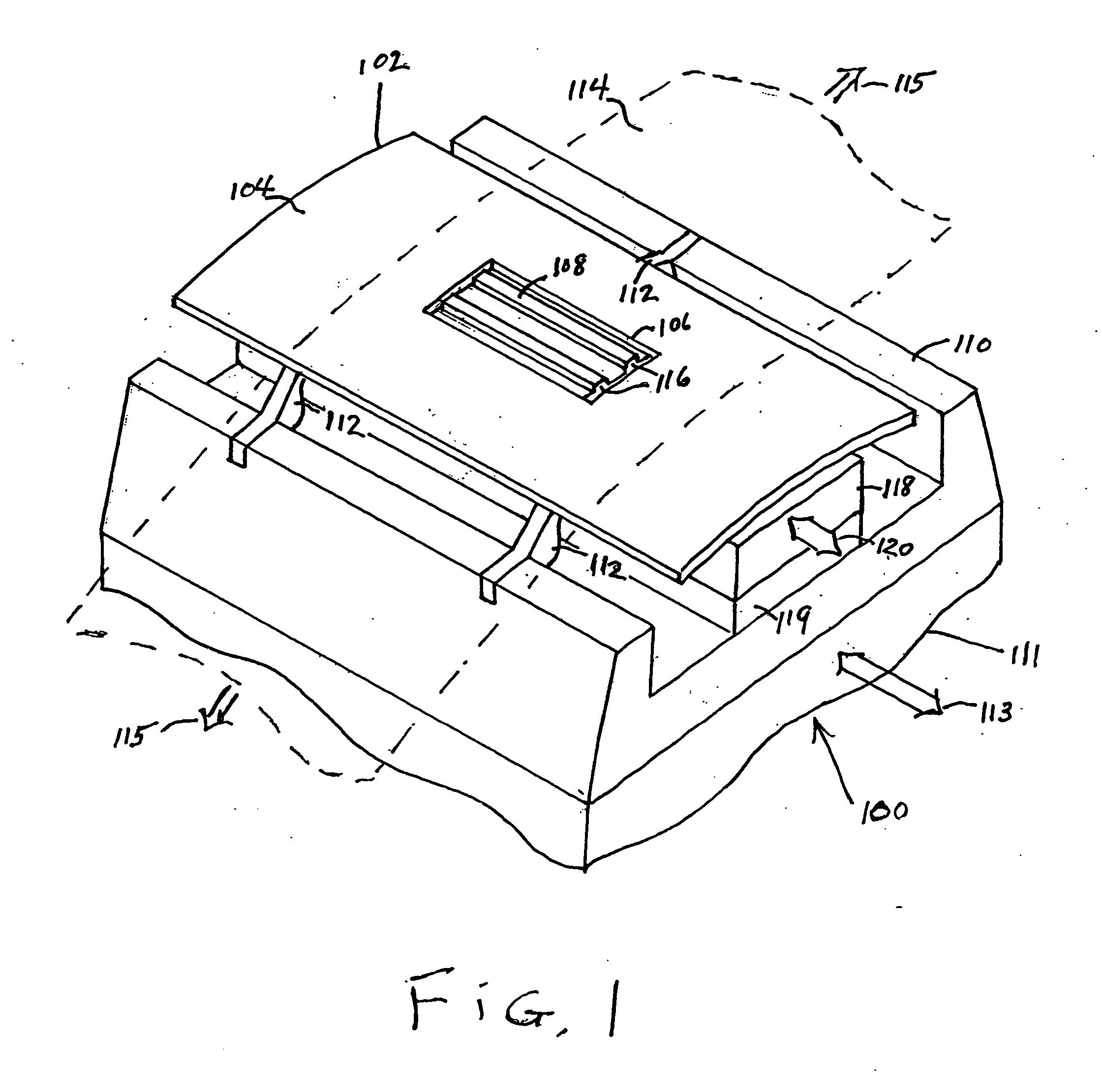
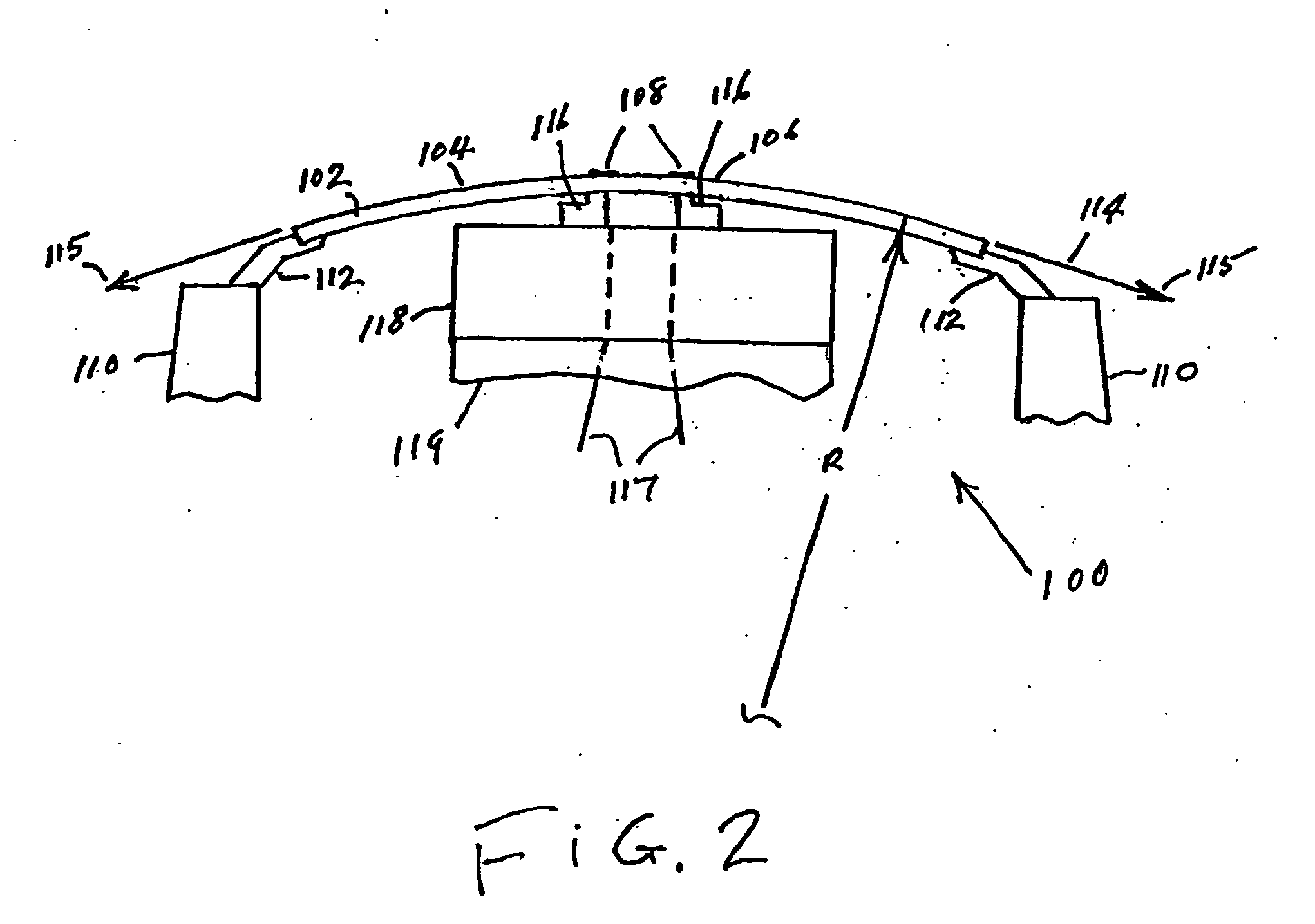
[0018]FIG. 1 is a perspective view, not to scale, of a first embodiment of the tape recording head 100 of the present invention. FIG. 2 shows an end view, not to scale, of the tape recording head 100. Referring to FIGS. 1 and 2, the tape recording head 100 comprises a support plate 102 having a cylindrical contoured surface 104 with a rectangular opening 106 which allows head chips 108 to protrude far enough to allow proper head tape contact for recording. The cylindrical contoured surface 104 has a substantially rectangular shape. The support plate 102 is fixed by supports 112 on a base carrier 110 that is rigidly mounted on a coarse actuator 111 so that the support plate 102 and coarse actuator move together in a direction perpendicular to the direction of the linear motion 115 of recording tape 114 (shown in phantom) over recording head 100. The head chips 108 comprising rowbar substrates 116 containing a multiplicity of recording transducers are supported on a carrier 118 mounte...


PUM

PropertyMeasurementUnit
radiusaaaaaaaaaa
protrusion distanceaaaaaaaaaa
radiusaaaaaaaaaa

Abstract

A tape recording head is provided comprising a support plate having a contoured surface with an opening in the contoured surface which allows head chips to protrude far enough to allow proper head tape contact for recording. The support plate is fixed on a coarse actuator so that the support plate and coarse actuator move together perpendicular to the motion of the recording tape. The head chips comprising rowbar substrates containing a multiplicity of recording elements are supported on a carrier mounted on a fine actuator and are not fixed to the support plate to allow low mass fine actuation.

Description

BACKGROUND OF THE INVENTION [0001] 1. Field of the Invention [0002] This invention relates to magnetic tape recording heads, and more particularly to a tape recording head with a support plate having a contoured surface to support the recording tape passing over the recording head. [0003] 2. Description of the Related Art [0004] In magnetic storage systems, data is read from and written onto magnetic recording media utilizing magnetic transducers commonly referred to as magnetic heads. Data is written on the magnetic recording media by moving a magnetic recording head to a position over the media where the data is to be stored. The magnetic recording head then generates a magnetic field, which encodes the data into the magnetic media. Data is read from the media by similarly positioning the magnetic read head and then sensing the magnetic field of the magnetic media. Read and write operations are independently synchronized with the movement of the media to ensure that the data can b...

Claims


Application Information

Patent Timeline
Patent Type & Authority Applications(United States)
IPC IPC(8): G11B5/008G11B5/105G11B5/56G11B15/62G11B21/24
CPCG11B5/00813G11B5/105G11B21/24G11B15/62G11B5/56
Inventor BISKEBORN, ROBERT GLENN
Owner META PLATFORMS INC
Why Eureka
Try Eureka