Photochromic film material

a technology of photochromic materials and film layers, applied in the field of photochromic film layers, can solve the problems of insufficient use of photochromic materials in products involving long exposure to sunlight, and the use of photochromic materials is very limited, so as to minimize the penetration of short wavelength uv radiation and enhance the resistance to light fatigue

Inactive Publication Date: 2005-06-23
LINTEC CORP
View PDF2 Cites 98 Cited by
  • Summary
  • Abstract
  • Description
  • Claims
  • Application Information

AI Technical Summary

Benefits of technology

[0012] The photochromic light transmitting sheet of the invention having unique combinations of ultraviolet absorbing and infrared filtering properties and materials can be tailored to provide measurable changes in transmission while providing a longer useful life and photochromic stability to an enhanced resistance to light fatigue. The sequenc

Problems solved by technology

The use of photochromic materials, however, has been very limited due to degradation of the photochromic property of the material from continued exposure to ultravi

Method used


Image

  • Photochromic film material
  • Photochromic film material
  • Photochromic film material

Examples


examples

[0033] The following examples are presented to illustrate the advantages of the present invention and to assist one of ordinary skill in making and using the same. These examples are not intended in any way otherwise to limit the scope of the disclosure.

[0034] The following examples provide exemplary photochromic filters according to the invention. All parts in the adhesive formulations are by weight unless otherwise noted. The sheet numbers referenced below correspond to the sheet numbers in Table II.

example i

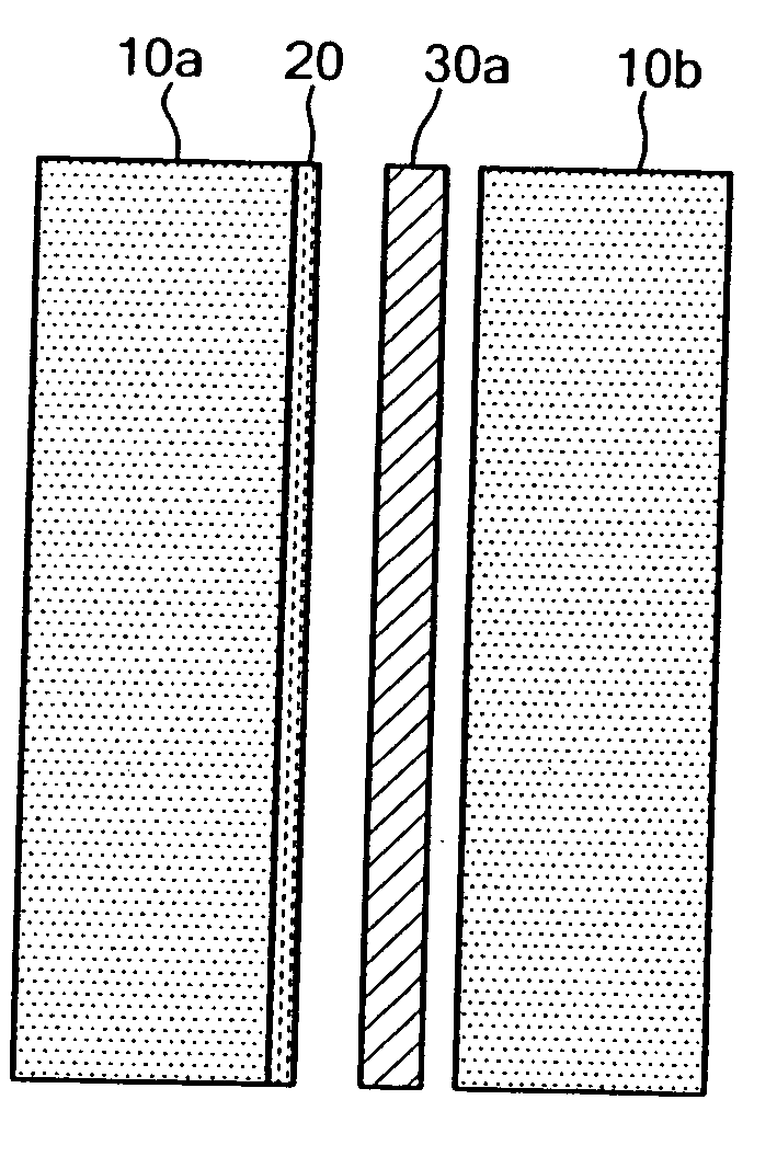
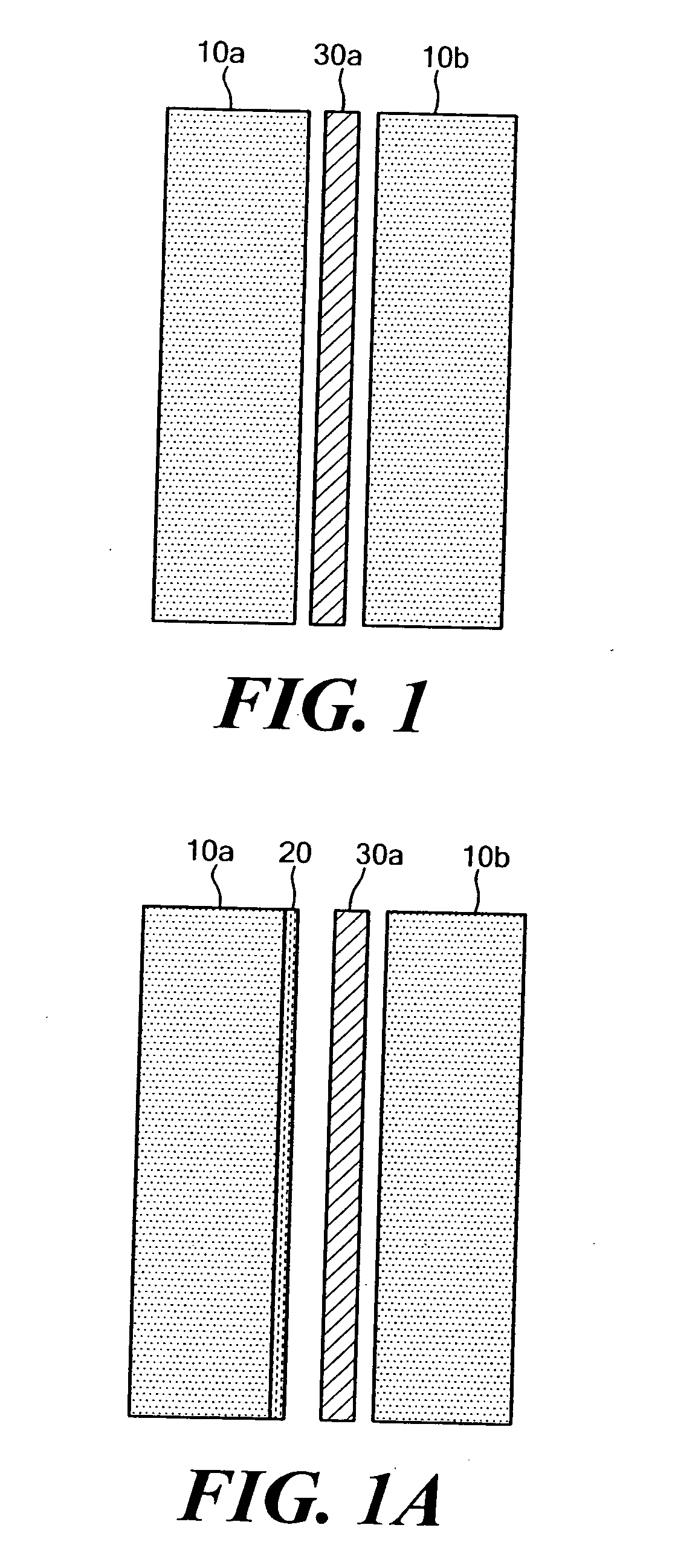
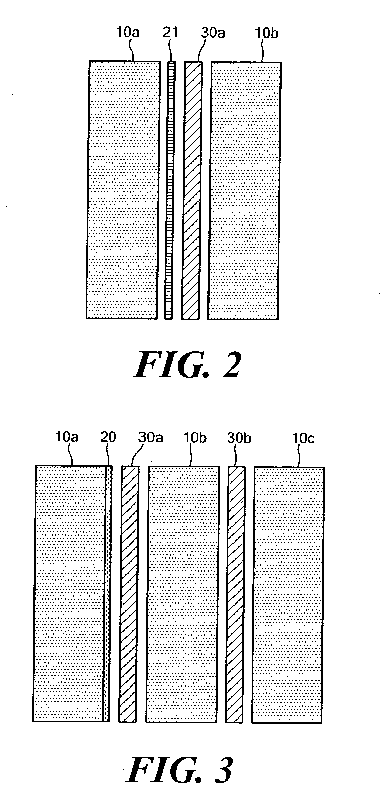
[0035] A 25 micrometer foil of clear polyethylene terepthalate (PET) was coated on one side with a 20% solution of an aliphatic urethane laminating adhesive in 1:1:1 by weight ethanol / toluene / methyl ethyl ketone solvent blend. This laminating adhesive consisted of 30 gms adhesive resin solution, 0.5 gm di-epoxide curing agent, 0.30 gm spiroindoline oxazine dye (commercially available material from PPG Chemicals, also known as “Photosol Blue 02-65”). The laminating adhesive solution was designated as “LAM-0”, meaning no light stabilizers.

[0036] The laminating adhesive coating solution was applied to the substrate surface using a Mayer Bar, the solvents were dried off with a forced hot air gun at a dry coating thickness of 2-8 microns, equivalent to about 2-8 gms per square meter of surface area.

[0037] The rheological properties of the photochromic adhesive solutions tend to yield unacceptable smoothness of the dried coating at thickness greater than 10 microns. This optical defect ...

example ii

[0040] A modification of LAM-0 was made by incorporating into the mix an equivalent amount (with respect to the dye) of UV absorbers 2-ethylhexyl p-methoxycinnamate, also called “Uvinul 3088” manufactured by BASF Corporation, and hindered amine light stabilizer called “Tinuvin 5050” available from Ciba-Geigy Specialty Chemicals. This light-stabilized adhesive mix was designated as “LAM-1” and was used to make another 3-ply laminate. [0041] [PC—Sheet #02]→PET / LAM-1 / PET / LAM-0 / PET


PUM

PropertyMeasurementUnit
Nanoscale particle sizeaaaaaaaaaa

Abstract

The invention is directed to a photochromic material that filters, from solar radiation, near infrared radiation and sufficient portions of ultraviolet radiation while transmitting actinic radiation in the wavelength range of about 341±5 nm. The light-transmitting photochromic material provides light and heat stability to achieve a longer useful life. This photochromic material is preferably incorporated in a multilayered structure with constituents provided on or contained within one or more layers to enhance the resistance to light fatigue.

Description

CROSS REFERENCE TO RELATED APPLICATIONS [0001] N / A STATEMENT REGARDING FEDERALLY SPONSORED RESEARCH OR DEVELOPMENT [0002] N / A BACKGROUND OF THE INVENTION [0003] Photochromic materials are known and exhibit a change in light transmission or color in response to exposure to actinic radiation in the spectrum of sunlight. Removal of the incident radiation causes these materials to revert back to their original transmissive state. [0004] Such photochromic materials have product applications for sunglasses, graphics, ophthalmic lenses, solar control window films, security and authenticity labels, and many others. The use of photochromic materials, however, has been very limited due to degradation of the photochromic property of the material from continued exposure to ultraviolet (UV) light radiation, particularly short wavelengths (<400 nanometers (nm)), and to infrared (IR) radiation (>780 nm). This degradation is known as “light fatigue” and is caused by chemical decomposition of ...

Claims


Application Information

Patent Timeline
IPC IPC(8): B32B7/02B32B15/04B32B27/06B32B27/20B32B27/36G02B5/23G03C
CPCG02B5/23B32B7/02Y10T428/31681Y10T428/31504Y10T428/31786Y10T428/31678G03C1/29B32B7/12B32B2307/40B32B2307/71B32B27/08B32B27/36
Inventor GARCIA, LEO M.
Owner LINTEC CORP
Why Eureka
Try Eureka