
White organic light emitting device

a light-emitting device and organic technology, applied in the direction of discharge tube luminescence screen, natural mineral layered products, transportation and packaging, etc., can solve the problems of difficult fabrication, low efficiency, luminescence property, etc., and achieve the effect of simple structure and high organic light-emitting efficiency

Inactive Publication Date: 2005-06-23
ELECTRONICS & TELECOMM RES INST
View PDF19 Cites 22 Cited by
  • Summary
  • Abstract
  • Description
  • Claims
  • Application Information

AI Technical Summary

Benefits of technology

[0014] The present invention is directed to implementation of a high efficiency of organic light emitting device having a white luminescence property by means of a simple structure using a single emission layer.
[0015] The present invention is also directed to implementation of a three-wavelength white organic light emitting device having high color reproduction by means of a simple structure using a single emission layer.
[0016] One aspect of the present invention is to provide a white organic light emitting device including: an anode and an cathode to which a bias is applied; and an emission layer into which a host having a blue luminescence property and a first guest exhibiting an orange or red luminescence property are doped, a hole blocking layer for confining holes in the emission layer, and an electron transport layer having a green luminescence property, wherein the emission layer, the hole blocking layer, and the electron transport layer are stacked between the anode and the cathode Preferably, the white organic light emitting device is additionally doped with a second guest capable of improving efficiency of the blue light emitting material.

Problems solved by technology

In this case, the three-wavelength white organic light emitting device, however, has a complicated structure, thus causing problems of difficult fabrication and low efficiency.
However, since the luminescence property-of a green color is low in comparison with those of red and blue colors, the two-wavelength white organic light emitting device has poor color reproduction.
For these reasons, the two-wavelength white organic light emitting device is difficult to apply to applied fields where both the color purity and the color reproduction are required to be high, such as a display field, an illumination field, and so forth.

Method used


Image

  • White organic light emitting device

Examples


Embodiment Construction

[0024] Hereinafter, an exemplary embodiment of the present invention will be described in detail. However, the present invention is not limited to the embodiments disclosed below, but can be implemented in various types. Therefore, the present embodiment is provided for complete disclosure of the present invention and to fully inform the scope of the present invention to those ordinarily skilled in the art.

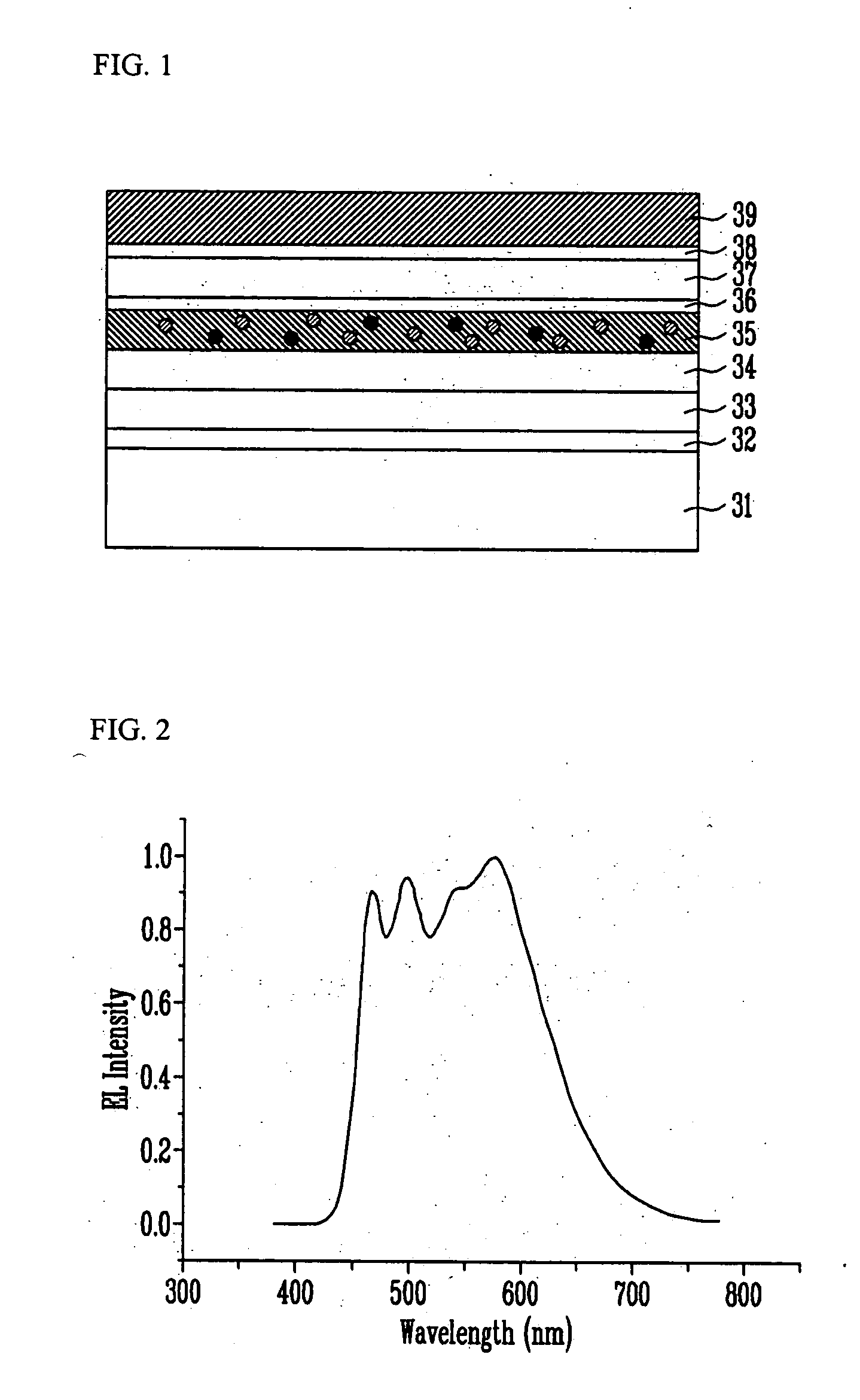
[0025]FIG. 1 is a cross-sectional view for explaining a white organic light emitting device according to the present invention.

[0026] An anode 32 of a transparent electrode material is formed on a substrate 31 made of transparent grass, quartz, or plastic. A hole injection layer (HIL) 33 helping injection of holes is formed on the anode 32. A hole transport layer (HTL) 34 is formed on the hole injection layer 33, wherein the HTL 34 causes the holes to have good mobility and to facilitate transportation to an emission layer 35.

[0027] On the HTL 34 is formed the emission layer 35...


PUM

PropertyMeasurementUnit
band gapaaaaaaaaaa
band gapaaaaaaaaaa
band gapaaaaaaaaaa

Abstract

Provided is a white organic light emitting device capable of realizing characteristics of excellent color purity and high efficiency through structural simplification. The white organic light emitting device includes an emission layer, a hole blocking layer and an electron transport layer which are deposited between an anode and an cathode to which a bias is applied, wherein a host having a blue luminescence property and a first guest having any one of orange and red luminescence properties are doped into the emission layer, and a material having a green luminescence property is included in the electron transport layer.

Description

CROSS-REFERENCE TO RELATED APPLICATION [0001] This application claims priority to and the benefit of Korean Patent Application Nos. 2003-94755, filed on Dec. 22, 2003, and 2004-52214, filed on Jul. 6, 2004, the disclosure of which is incorporated herein by reference in its entirety. BACKGROUND [0002] 1. Field of the Invention [0003] The present invention relates to a white organic light emitting device used as a display device, and more particularly, to a white organic light emitting device capable of exhibiting characteristics of excellent color purity and high efficiency through structural simplification. [0004] 2. Discussion of Related Art [0005] With development of the telecommunication industry, display devices have been rapidly increased in demand. Currently, the display device is required to be light in weight, thin in thickness and high in resolution. In line with this requirement, there have been developed display devices applying either liquid crystal display (LCD) propert...

Claims


Application Information

Patent Timeline
Patent Type & Authority Applications(United States)
IPC IPC(8): C09K11/06H05B33/14H05B33/20H10K99/00
CPCH01L51/0037H01L51/005H01L51/0051H01L51/0059Y10T428/24942H01L51/0078H01L51/5036H01L51/5048H01L51/5096H01L51/0062H10K85/1135H10K85/611H10K85/60H10K85/649H10K85/631H10K85/311H10K50/125H10K50/14H10K50/18
Inventor CHU, HYE YONGLEE, JEONG IK
Owner ELECTRONICS & TELECOMM RES INST
Learn More