Fuel cell system

a fuel cell and system technology, applied in the direction of fuel cells, solid electrolyte fuel cells, electrical equipment, etc., can solve the problems of water vapor in the catalytic burner not working properly, moisture may condense on the catalyst surface, and the water vapor in the catalytic burner may saturate, so as to achieve simple composition and reduce water vapor in the catalytic burner

Inactive Publication Date: 2005-06-23
NISSAN MOTOR CO LTD
View PDF9 Cites 16 Cited by
  • Summary
  • Abstract
  • Description
  • Claims
  • Application Information

AI Technical Summary

Benefits of technology

[0005] Since the water vapor in the catalytic burner can be transposed to cathode gas and the water vapor in the catalytic burner can be decreased, a catalyst carries out activity quickly at the time of starting of the fuel cell. Moreover, since it becomes unnecessary to provide the blower that takes in air from the exterior to the catalytic burner, the fuel cell system becomes simple in composition.

Problems solved by technology

However, in the fuel cell system mentioned above, in the case of rainy weather, or in high humidity, since water vapor is contained in the air which is inhaled by the blower, a catalytic burner does not function properly.
Furthermore, when a catalytic burner is filled with high humidity air, when a fuel cell stops and temperature falls, the water vapor in a catalytic burner may saturate, and moisture may condense on the catalyst surface.
When moisture adheres to the catalyst surface, it becomes impossible for the catalytic burner to burn hydrogen.
Moreover, because a car has space restrictions, the system which needs both the compressors which supply air to a fuel cell and the blower for burners is not desirable.

Method used


Image

  • Fuel cell system
  • Fuel cell system
  • Fuel cell system

Examples


first embodiment

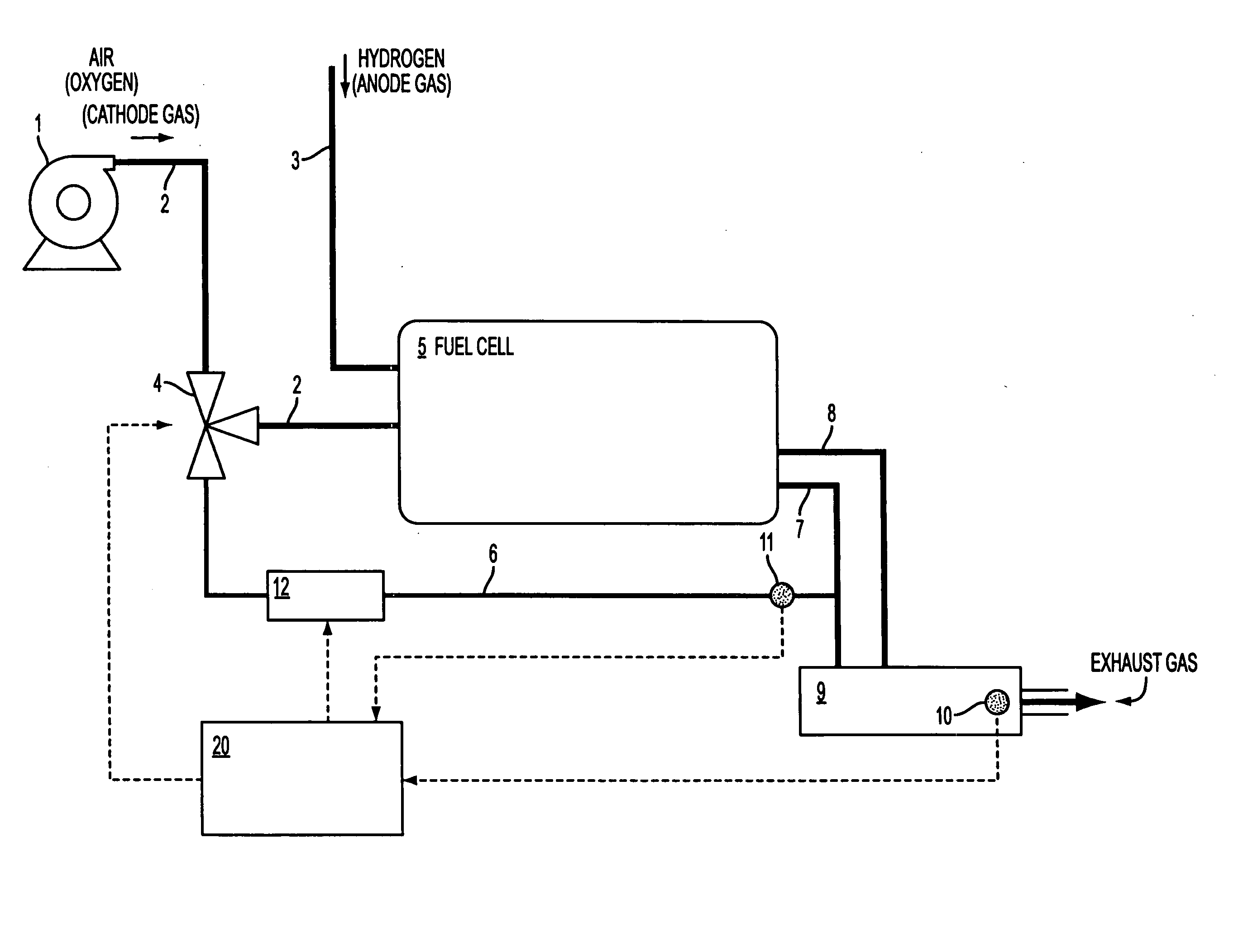
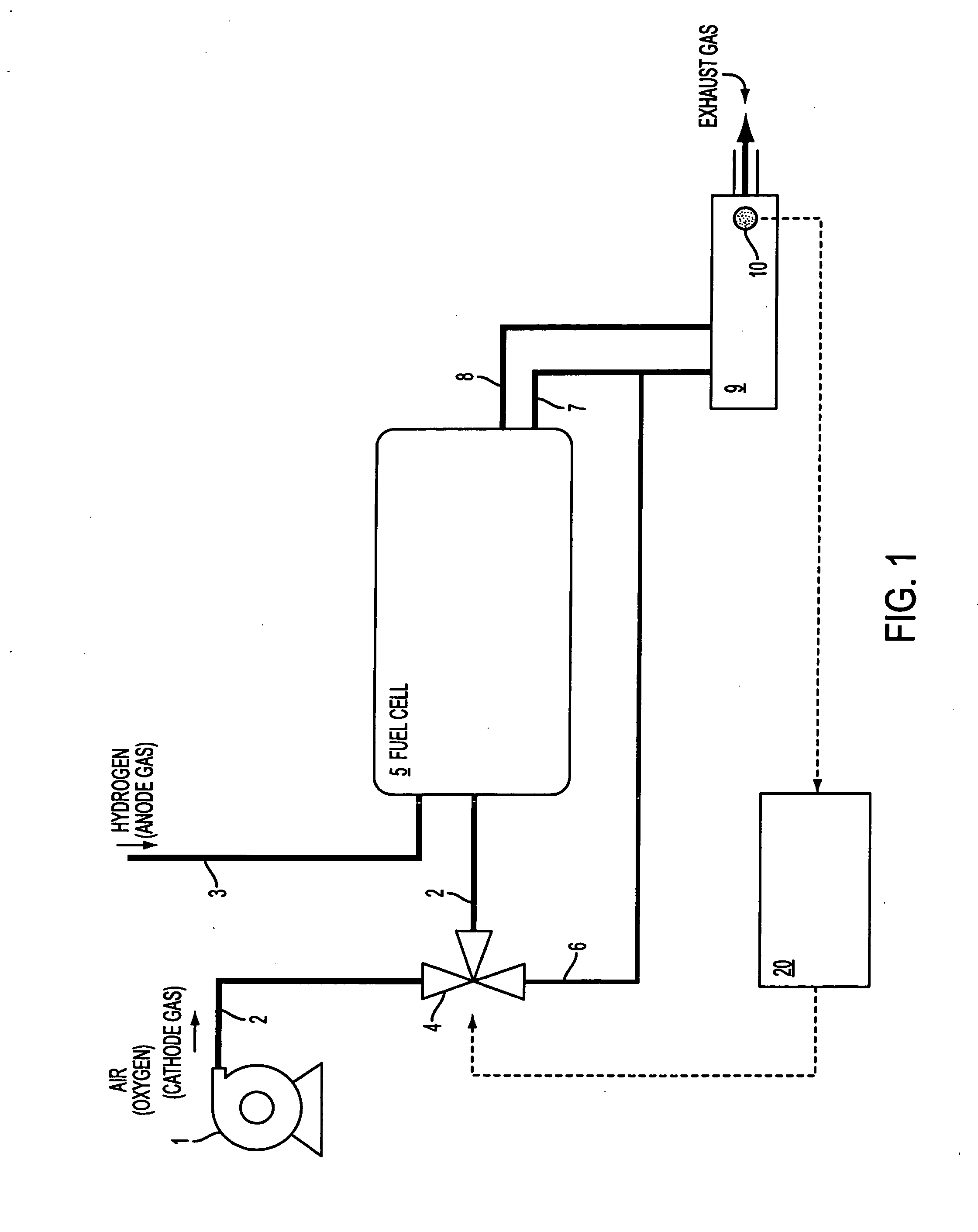
[0013]FIG. 1 shows the composition of the operation of the fuel cell system of this invention.

[0014] As shown in FIG. 1, a fuel cell system is comprised of a compressor 1 which supplies air (cathode gas) including oxygen gas, and a cathode line 2 which supplies air compressed by the compressor 1 to a fuel cell 5, and an anode line 3 which supplies hydrogen (anode gas) to the fuel cell 5, and a catalytic burner 9 which burns discharge hydrogen from the fuel cell 5, and a cathode exhaust gas line 7 which discharges the oxygen after a reaction from the fuel cell 5 to the catalytic burner 9, and an anode exhaust gas line 8 which discharges the hydrogen after a reaction from the fuel cell 5 to the catalytic burner 9, and an exhaust temperature sensor 10 which measures the temperature of the exhaust gas discharged from the catalytic burner 9.

[0015] A cathode switch valve 4 is provided in the middle of the cathode line 2. The cathode switch valve 4 switches the flow of oxygen to the catho...

third embodiment

[0027]FIG. 5 shows the composition of the operation of the fuel cell system of this invention. In this embodiment, the fuel cell system has an anode switch valve 13. The anode switch valve 13 switches the flow of hydrogen to the anode line 3 or an anode bypass line 14. The anode bypass line 14 is connected to the anode exhaust gas line 8.

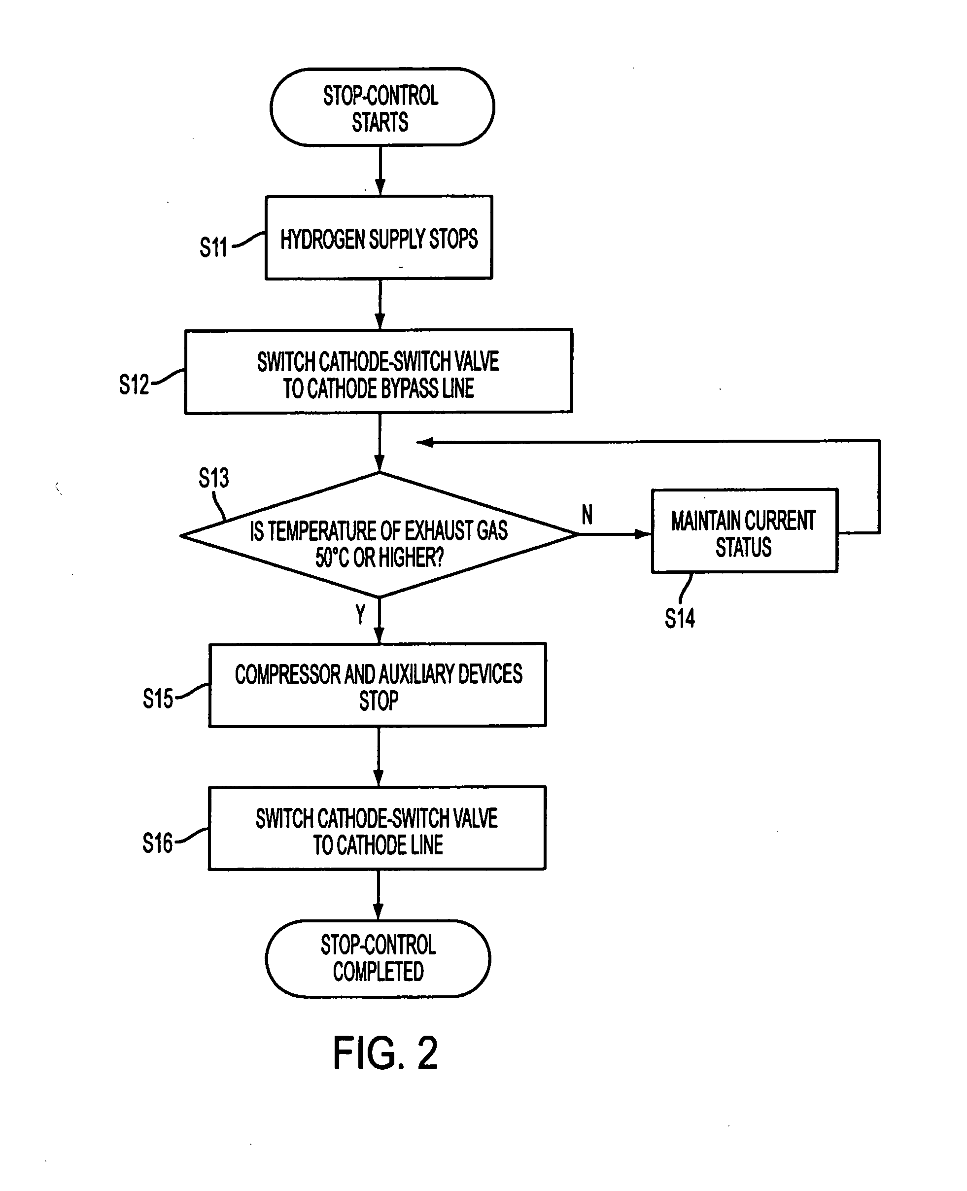
[0028] Below, the concrete control logic of a controller 20 is explained along with the flow chart shown in FIG. 6.

[0029] Stop control of the fuel cell system is performed as follows. First, in step S31, the cathode switch valve 4 is switched to the cathode bypass line 6. The air does not go through the fuel cell 5 but instead, the non-saturated air is supplied to the catalytic burner 9.

[0030] In step S32, the anode switch valve 13 is switched to the anode bypass line 14. The hydrogen that does not go through the fuel cell 5, i.e., the unreacted hydrogen, is supplied to the catalytic burner 9. In step S33, the catalytic burner 9 operates so that t...


PUM

PropertyMeasurementUnit
timeaaaaaaaaaa
electrical poweraaaaaaaaaa
temperatureaaaaaaaaaa

Abstract

A fuel cell generates electric power by the electrochemical reaction of hydrogen and the oxygen in air. After the hydrogen discharged without being consumed by an anode is burned in a burner, it is discharged out of a fuel cell system. Therefore, the fuel cell system has a cathode switch valve in the middle of the cathode line, and when the fuel cell system stops, non-saturated air of a compressor bypasses the fuel cell, and supplies the air to the catalytic burner. Although the cathode exhaust gas of saturated water vapor is circulating to the catalytic burner at the time of regular operation of the fuel cell, the non-saturated air which bypasses the fuel cell and is supplied can replace the inside of the catalytic burner with dry air. Therefore, the amount of water vapor in the catalytic burner is decreased at the time of a stop, and the catalyst is quickly activated at the time of re-starting.

Description

BACKGROUND OF THE INVENTION [0001] The fuel cell system currently described by JP2002-343391A is equipped with a catalytic burner which burns hydrogen discharged from a Polymer Electrolyte Fuel Cell [PEFC] in order to prevent discharge of hydrogen to the atmosphere. While the PEFC using a solid high polymer electrolyte has a low temperature of operation and handling is easy, the high polymer electrolyte film has the characteristic of not fully demonstrating hydrogen ion conductivity, if not fully humidified. The solid high polymer type fuel cell has a stratified structure that alternately piles up a separator and a resin film with hydrogen conductivity. The separator forms the hydrogen channel in one side, and forms the air channel in an opposite side. The fuel cell system is comprised of a hydrogen supply device with which a fuel cell system supplies hydrogen as fuel gas, a compressor that supplies air as oxidizer gas, and a fuel cell stack which has an anode and a cathode. However...

Claims


Application Information

Patent Timeline
Patent Type & Authority Applications(United States)
IPC IPC(8): H01M8/04H01M8/10H01M8/06
CPCH01M8/04089H01M8/04373H01M8/04738Y02E60/50H01M8/04776H01M8/04955H01M8/0662H01M8/04753
Inventor SHOJI, TADASHIHAMADA, KARUKI
Owner NISSAN MOTOR CO LTD
Why Eureka
Try Eureka