Heater, fixing unit and image forming apparatus

Inactive Publication Date: 2005-06-30
RICOH KK
View PDF15 Cites 69 Cited by
  • Summary
  • Abstract
  • Description
  • Claims
  • Application Information

AI Technical Summary

Benefits of technology

[0027] Another object of the present invention is to provide a heater operable with a main power supply unit and a chargeable auxiliary power supplying unit, comprising a heater part having one or a plurality of heater elements configured to receive power from the main and auxiliary power supplying units; and a controller configured to change a usage of power and/or an amount of power stored in the auxiliary power supply unit based on the amount of power stored in the auxiliary power supply unit. According to the heater of the present invention, it is possible to reduce the waiting time that is required until the temperature of a fixing unit reaches the predetermined fixing temperature when the main power supply unit is turned ON, reduce the waiting time that is required for the temperature of the fixing unit to reach the predetermined fixing temperature from the standby state such as a sleep mode and a power save mode of an image forming apparatus, and improve the productivity when continuously carrying out an image forming process with respect to the consecutively supplied recording media.
[0028] Still another object of the present invention is to provide a fixing unit comprising a heater operable with a main power supply unit and a chargeable auxiliary power supplying unit, the heater comprising a heater part having one or a plurality of heater elements configured to receive power from the main and auxiliary power supplying units; and a controller configured to change a usage of power and/or an amount of power stored in the auxiliary power supply unit based on predetermined information selected from a group consisting of an input voltage of the main power supply unit, an environment temperature and the amount of power stored in the auxiliary power supply unit. According to the fixing unit of the present invention, it is possible to reduce the waiting time that is required until the temperature of the fixing unit reaches the predetermined fixing temperature when the main power supply unit is turned ON, reduce the waiting time that is required for the temperature of the fixing unit to reach the predetermined fixing temperature from the standby state such as a sleep mode and a power save mode of an image forming apparatus, and improve the productivity when continuously carrying out an image forming process with respect to the consecutively supplied recording media.
[0029] A further object of the present invention is to provide an image forming apparatus comprising a fixing unit; the fixing unit comprising a heater operable with a main power supply unit and a chargeable auxiliary power supplying unit, and comprising a heater part having one or a plurality of heater elements configured to receive power from the main and auxiliary power supplying units, and a controller configured to change a usage of power and/or an amount of power stored in the auxiliary power supply unit based on predetermined information selected from a group consisting of an input voltage of the main power supply unit, an environment temperature and the amount of power stored in the auxiliary power supply unit; and a fixing part, heated by the heater part, and configured to fix an image on a recording medium that makes sliding contact with the heater part or pass close to the heater part. According to the image forming apparatus of the present invention, it is possible to reduce the waiting time that is required until the temperature of the fixing unit reaches the predetermined fixing temperature when the main power supply unit is turned ON, reduce the waiting time that is required for the temperature of the fixing unit to reach the predetermined fixing temperature from the standby state such as a sleep mode and a power save mode of the image forming apparatus, and improve the productivity when continuously carrying out an image forming process with respect to the consecutively supplied recording media.
[0030] Another object of

Problems solved by technology

Recently, environmental problems have become increasingly important, and proposals have been made to reduce the power (or energy) consumption of the image forming apparatuses such as copying machines and printers.
But according to this popularly employed method, a certain power must be supplied to the fixing unit even when the fixing unit is not in use, and surplus power is consumed thereby.
It is said that this power consumption in the standby state amounts to approximately 70% to approximately 80% of the total power consumption of devices, units and the like forming the image forming apparatus.
However, if the power consumption of the image forming apparatus in the standby state is set to zero, it will take a long time on the order of several minutes to several tens of minutes to raise the temperature of the heat roller of the fixing unit to the usable temperature of approximately 180° C., because the heat roller is a metal roller mainly made of iron, aluminum or the like having a large heat capacity.
Such a long waiting time required until the temperature of the heat roller reaches the usable temperature will make the image forming apparatus inconvenient to use for the user.
Consequently, the use of the 200 V power supply is not a generally applicable solution for reducing the time required to raise the temperature of the heat roller.
In other words, as long as the commercial power supply of 100 V and 15 A is used, it is difficult to raise the temperature of the heat roller within a short time since a maximum input energy is determined by the power supply.
Consequently, the power c

Method used


Image

  • Heater, fixing unit and image forming apparatus
  • Heater, fixing unit and image forming apparatus
  • Heater, fixing unit and image forming apparatus

Examples


first embodiment

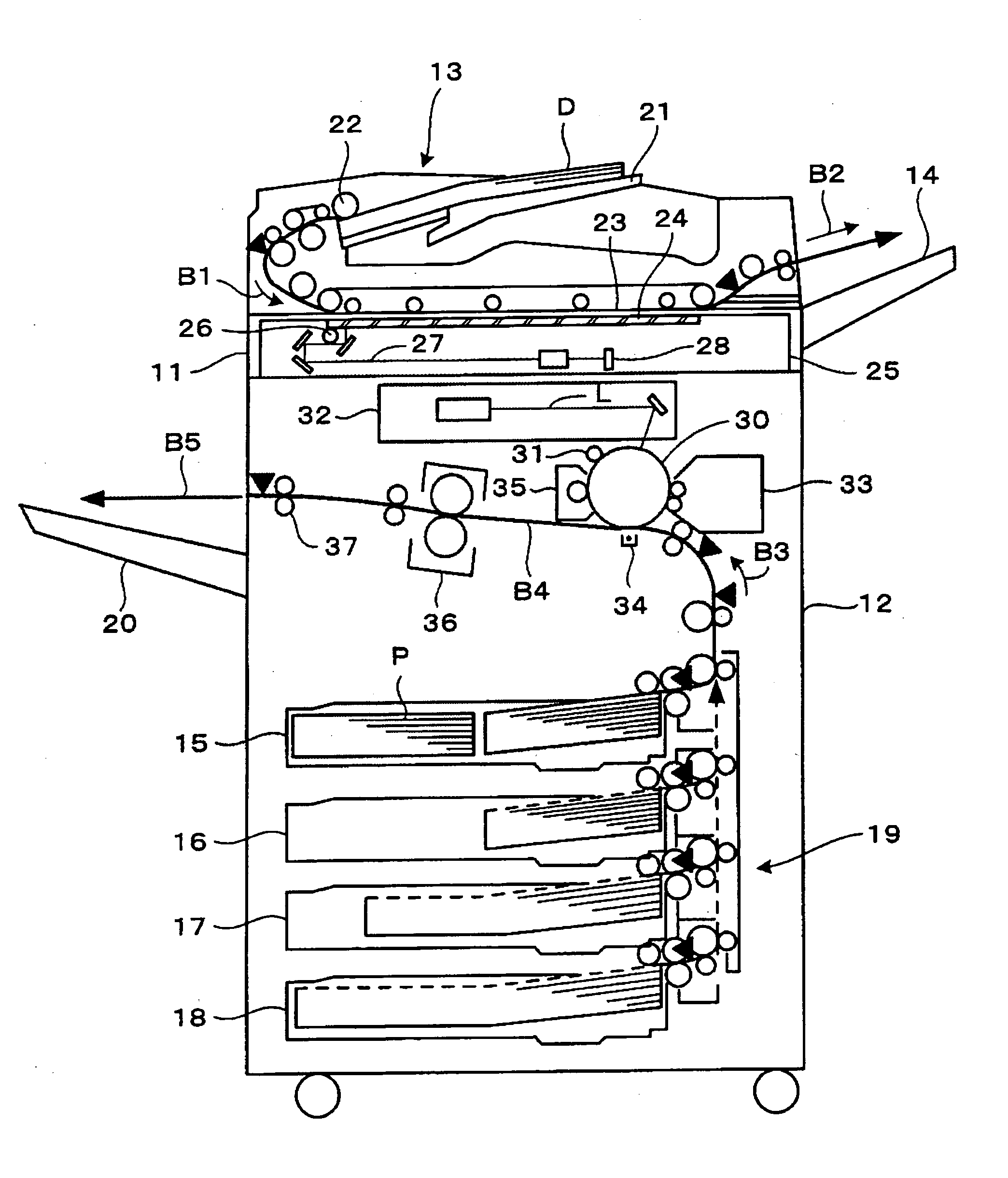
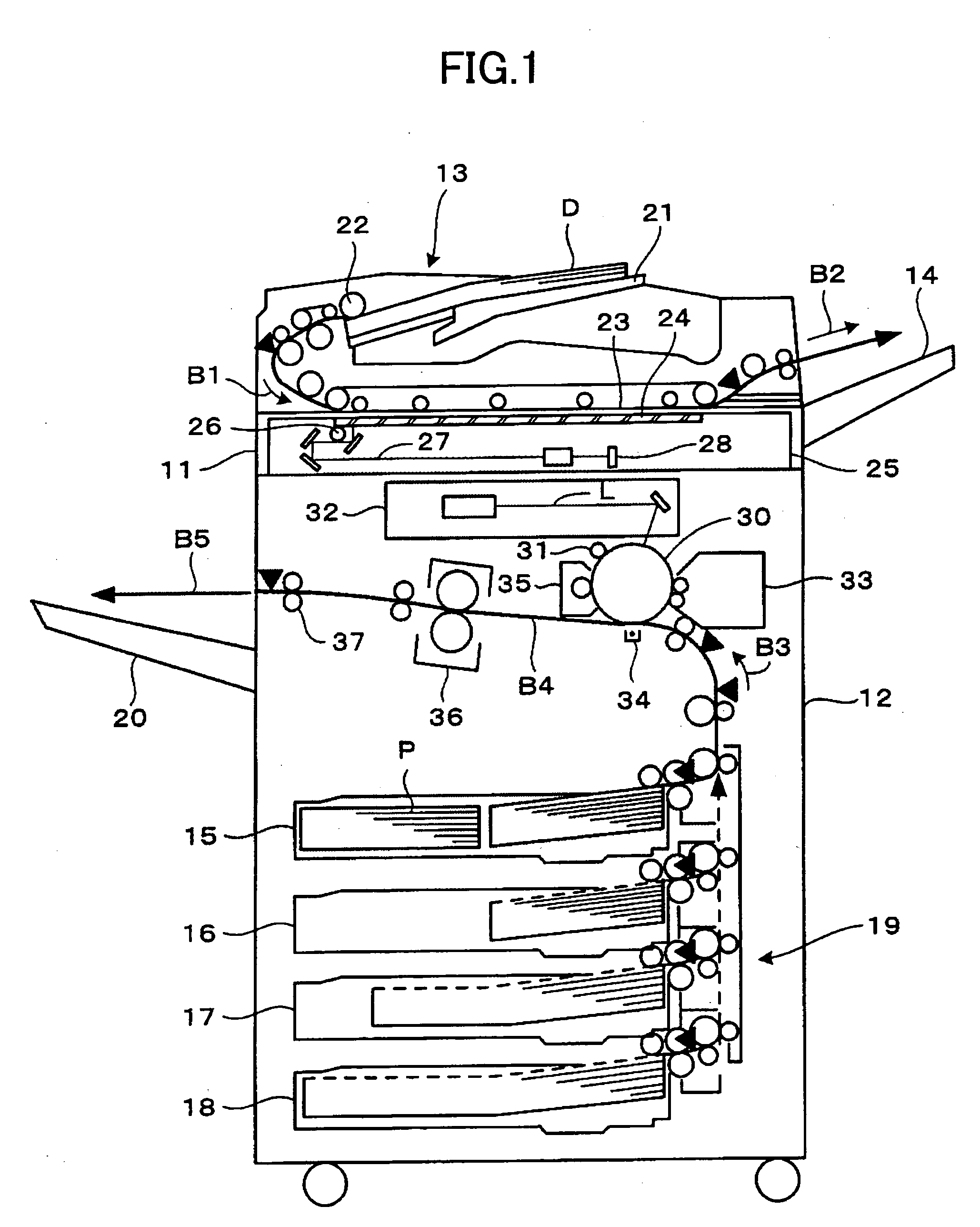
[0078]FIG. 1 is a cross sectional view conceptually showing a first embodiment of an image forming apparatus according to the present invention. In this embodiment, the image forming apparatus includes a document reading unit 11 which reads a document, an image forming unit 12 which forms an image on a recording medium (or recording sheet) P such as paper, an automatic document feeder (ADF) 13, a document eject tray 14 on which documents fed by the ADF 13 are stacked, a media supply unit 19 which is provided with media supply cassettes 15 through 18, and a media eject unit or media eject tray 20 on which recording media P are stacked. In this embodiment of the image forming apparatus, the present invention is applied to a copying machine employing the electrophotography technique. However, the present invention is similarly applicable to other image forming apparatuses such as printers, facsimile machines, and composite apparatuses having at least functions selected from a group con...

seventh modification

of First Embodiment

[0128] In a seventh modification of the first embodiment, the work time of a previous job is used for the information that is related to the heater 1 (or heater part 2), as the conditions used to vary the amount of power supplied from the capacitor C. A known timer or time measuring means (not shown) may be used to measure the work time of the previous job. In this case, the controller 8 varies the amount of power supplied from the capacitor C per unit time depending on the work time of the previous job, where the unit time is an arbitrary length of time.

[0129] For example, if the work time of the previous job is longer than a predetermined value, the controller 8 functions as an amount varying unit or means for reducing the amount of power supplied from the auxiliary power supply unit 4 per unit time. In other words, if the work time of the previous job is long, the temperature of the pressure roller 41 remains sufficiently high. In this case, the amount of heat...

second embodiment

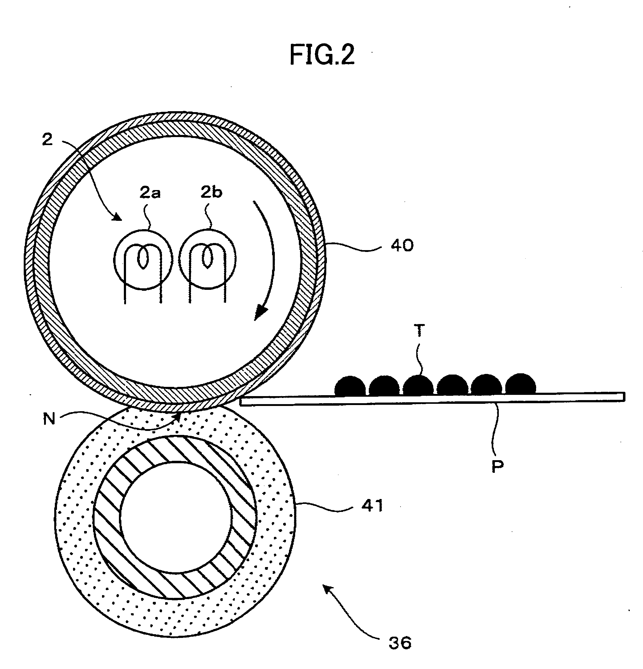
[0136] As described above, the surface temperature of the fixing roller in the standby state needs to be set to a low temperature from the point of view of reducing the power consumption. In addition, from the point of view of reducing the waiting time that is required for the surface temperature of the fixing roller to reach the predetermined fixing temperature from the standby state, it is necessary to reduce the heat capacity of the fixing roller.

[0137] However, compared to the fixing roller having a large heat capacity, the surface temperature of the fixing roller having a small heat capacity drops rapidly when the heat of the fixing roller is absorbed by the recording medium and the toner when fixing the toner image transferred on the recording medium. For this reason, the surface temperature of the fixing roller having the small heat capacity becomes lower than the lower limit of the fixing temperature, and an incomplete fixing easily occurs.

[0138] Hence, in order to prevent...


PUM

PropertyMeasurementUnit
Fractionaaaaaaaaaa
Capacitanceaaaaaaaaaa
Temperatureaaaaaaaaaa

Abstract

A heater is operable with a main power supply unit and a chargeable auxiliary power supplying unit. The heater includes a heater part having one or a plurality of heater elements to receive power from the main and auxiliary power supplying units, a detecting part to detect information related to the heater part, and a controller to vary an amount of power supplied from the auxiliary power supply unit to the heater part per unit time based on the information detected by the detecting part.

Description

BACKGROUND OF THE INVENTION [0001] This application claims the benefit of Japanese Patent Applications No.2003-408710 filed Dec. 8, 2003, No.2004-024785 filed Jan. 30, 2004, No.2004-024794 filed Jan. 30, 2004, and No.2004-028834 filed Feb. 5, 2004, in the Japanese Patent Office, the disclosures of which are hereby incorporated by reference. [0002] 1. Field of the Invention [0003] The present invention generally relates to heaters, fixing units and image forming apparatuses, and more particularly to a heater that is provided with a capacitor and is used to heat various materials or apparatuses, for example, a fixing unit that uses such a heater, and an image forming apparatus, such as a copying machine, a printer and a facsimile machine, that uses such a fixing unit and employs an electrophotography technique. [0004] 2. Description of the Related Art [0005] In an image forming apparatus such as a copying machine, an image is formed on a recording medium that may be plain paper, OHP o...

Claims


Application Information

Patent Timeline
IPC IPC(8): G03G15/00G03G15/20
CPCG03G15/2003G03G15/5004G03G15/205G03G2215/20G03G15/80
Inventor KISHI, KAZUHITOKATO, YASUHISAOKAMOTO, MASAMITSUKIOKA, YASUTADATAKAGI, HIROMASAMATSUSAKA, SUSUMUAMITA, AKIYASU
Owner RICOH KK
Why Eureka
Try Eureka