
Radio frequency semiconductor device and method of manufacturing the same

Active Publication Date: 2005-06-30
KEY FOUNDRY CO LTD
View PDF1 Cites 55 Cited by
  • Summary
  • Abstract
  • Description
  • Claims
  • Application Information

AI Technical Summary

Benefits of technology

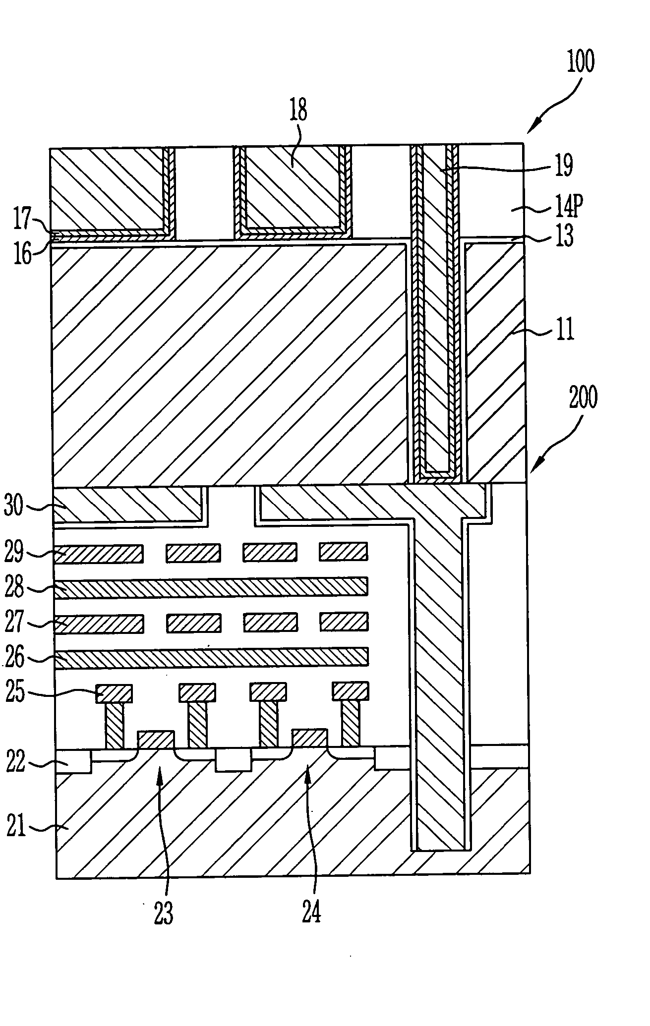
[0017] According to one of the guide lines for applying passive components to a radio frequency semiconductor device such as an RF-CMOS, Bipolar / SiGe and BiCMOS, in the case of a multi-layer metal wiring structure, an inductor must be formed on a top metal layer in order to minimize a parasitic capacitance to a substrate. In addition, a trench is inserted into the inductor and a thickness of an insulation layer is increased so as to overcome decoupling. The present invention is directed to a radio frequency integrated circuit which can minimize a parasitic capacitance by sufficiently increasing a distance between a semiconductor substrate on which elements have been formed and an inductor, by forming the inductor on a special wafer according to a chip scale integrated process (CIP) which is a 3D integration technology, and bonding the wafer onto another wafer on which the logic elements have been formed, and a method for manufacturing the same.

Problems solved by technology

However, in both the RF-CMOS and the Bipolar / BiCMOS, the inductor has a low quality factor (hereinafter, referred as ‘Q’).
However, if a width of the metal lines excessively increases, the inductor area increases, which results in a high parasitic capacitance and substrate loss.
However, there is a limitation to increase a distance between the substrate and the inductor when the inductor is formed by the damascene process, so that it is difficult to minimize a parasite capacitance to the substrate.
However, a Q value obtained by the single layer metal inductor is limitative.
In order to form a thicker metal inductor, a number of processes increases, and process failure occurs due to increase of entire height topology.
That is, it is difficult to form the thicker metal inductor on an on-chip.
However, the structure and properties of the inductor are deteriorated during a process for forming a uniform depth of inductor lines by double exposure or a process for forming a passivation layer after removing the photoresist layer.
A very complicated device having various functions is required for the future electronic system.
It implies a yield problem by integration of the multifunctional device, large expenses by complexity of the device, and technical limits.
In addition, wiring between sub systems has limits due to performance, muti-functions and reliability of the micro-electronic system.
Such factors are regarded as critical performance bottlenecks of the future IC generation.

Method used


Image

  • Radio frequency semiconductor device and method of manufacturing the same
  • Radio frequency semiconductor device and method of manufacturing the same
  • Radio frequency semiconductor device and method of manufacturing the same

Examples


Embodiment Construction

[0026] A radio frequency integrated circuit and a method for manufacturing the same in accordance with a preferred embodiment of the present invention will now be described in detail with reference to the accompanying drawings.

[0027] In the case that it is described that one film is disposed ‘on’ another film or a semiconductor substrate, one film can directly contact another film or the semiconductor substrate, or the third film can be positioned between them. In the drawings, a thickness or size of each layer is exaggerated to provide clear and accurate explanations. Wherever possible, the same reference numerals will be used throughout the drawings and the description to refer to the same or like parts.

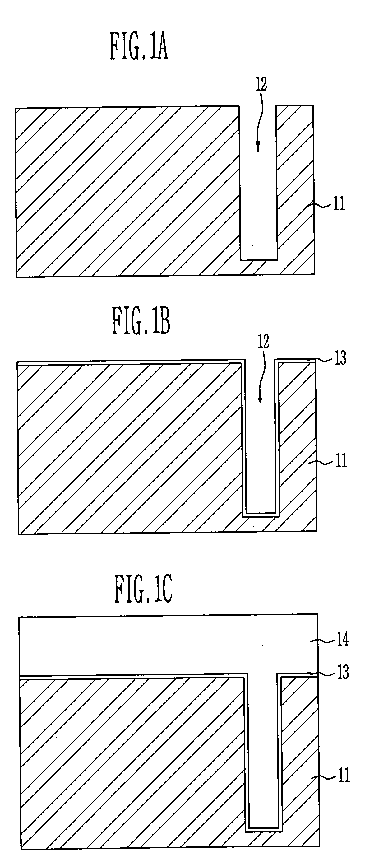
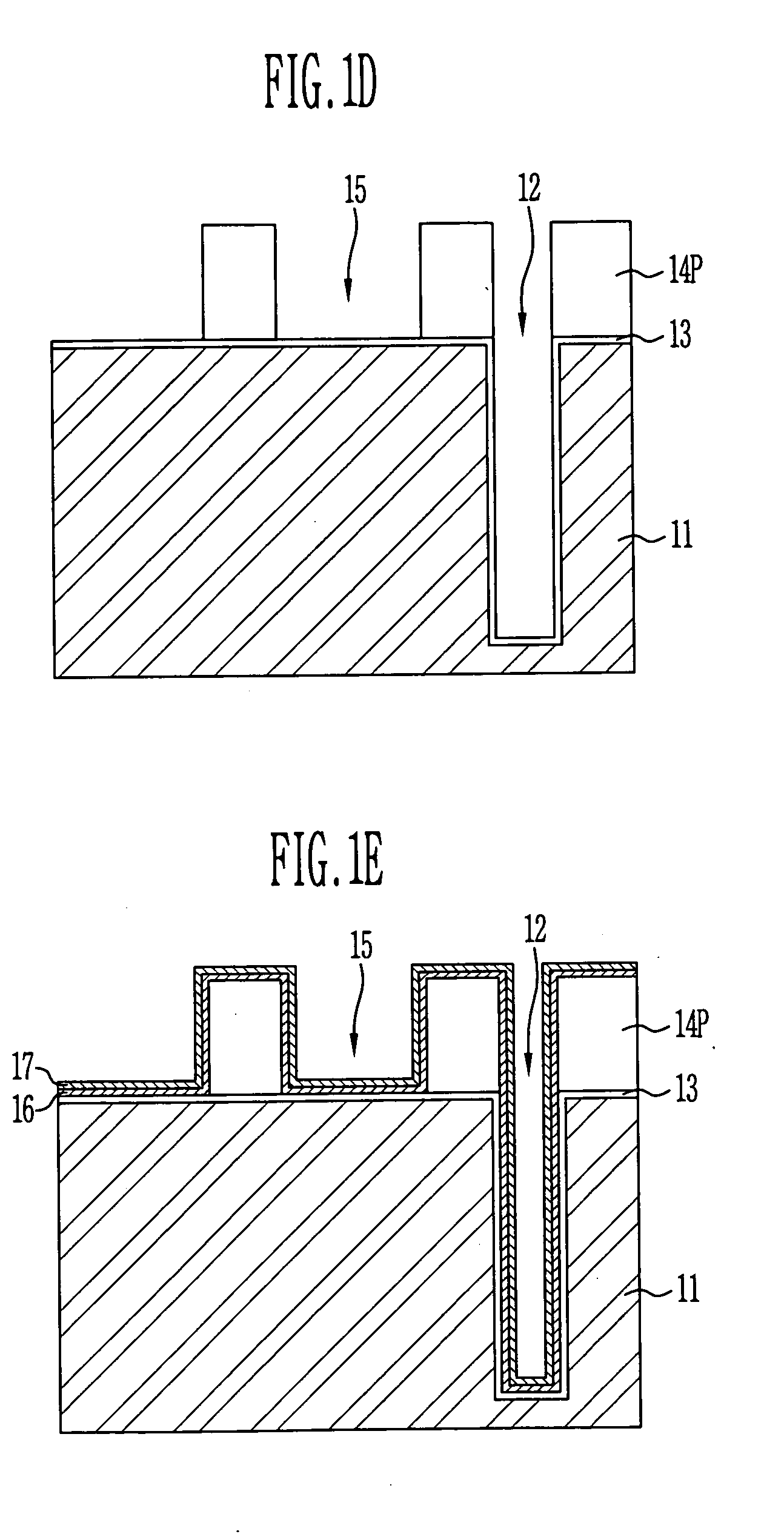
[0028]FIGS. 1A to 1G are cross-sectional views illustrating a method for forming an inductor having a via contact plug on a first wafer to form a radio frequency semiconductor device such as an RF-CMOS, Bipolar / SiGe and BiCMOS in accordance with the preferred embodiment of the pr...


PUM


Abstract

The present invention discloses a high frequency device including a first wafer providing an inductor having via contact plugs passing through the first wafer and a second wafer bonded to the first wafer, wherein the second wafer provides logic devices and inductor connection lines on an upper side thereof.

Description

BACKGROUND [0001] 1. Field of the Invention [0002] The present invention relates to a radio frequency integrated circuit, and a method for manufacturing the same, and more particularly to, a radio frequency integrated circuit capable of minimizing a parasitic capacitance by sufficiently increasing a distance between a semiconductor substrate on which elements have been formed and an inductor, and a method for manufacturing the same. [0003] 2. Discussion of Related Art [0004] According to paradigm variations of information and communication fields, there are increasing demands for communications which can be performed irrespective of time and places. Wireless mobile communication fields have been rapidly developed, satisfying such demands. Radio frequency resources, and materials, devices and circuits operated at a radio frequency are required due to the development of the wireless communication. The radio frequency resources, materials, devices and circuits are used in a radio frequ...

Claims


Application Information

Patent Timeline
IPC IPC(8): H01L21/822H01L21/3205H01L23/48H01L23/52H01L23/522H01L23/532H01L25/065H01L27/04H01L27/06
CPCH01L23/481H01L23/5227H01L23/53223H01L23/53238H01L23/53266H01L25/0657H01L2924/0002H01L27/0688H01L2225/06541H01L2924/00H01L25/065
Inventor PYO, SUNG GYU
Owner KEY FOUNDRY CO LTD
Learn More