Passive thermal management for semiconductor laser based lidar transmitter

a laser based lidar transmitter and passive thermal management technology, applied in semiconductor lasers, instruments, using reradiation, etc., can solve the problems of reducing laser performance (e.g. peak power, wavelength shift, efficiency, etc., to reduce the temperature of the laser diode, minimize parasitic capacitance, and high thermal conductivity

Active Publication Date: 2022-06-23
BEIJING VOYAGER TECH CO LTD
View PDF5 Cites 0 Cited by
  • Summary
  • Abstract
  • Description
  • Claims
  • Application Information

AI Technical Summary

Benefits of technology

[0009]According to certain embodiments, the thermal via is connected to a conductive pad on the bottom of the printed circuit board. A solder paste connects the conductive pad to the thermal bridge. The thermal via can be multiple vias, each formed by electroplating copper in the via hole. The vias can have hollow centers, like standard electrical connection vias, or can be completely filled to produce a solid via that conducts more heat. The cross-section of each via is comparable to the cross-section of the trigger trace. This design has been shown to reduce the temperature of the laser diode significantly—from nearly 100° Celsius to only 10° Celsius.
[0010]In one embodiment, the thermal bridge is a layer or strip of Beryllium oxide (BeO), an electrical insulator with high thermal conductivity. The thermal bridge will add some parasitic capacitance, proportional to the size of the thermal bridge. Thus, the size of the thermal bridge is chosen to be large enough to provide sufficient heat transfer, but small enough to minimize the parasitic capacitance and its effect on the laser pulse.

Problems solved by technology

In a LiDAR system, the transmitter (e.g., laser diode) generally consumes a large portion of the total power as it is the fundamental “energy source”.
Inevitably, the amount of heat generated will also be very large due to this large power consumption.
This is a significant problem, particularly for multi-element laser sources that are running at a high repetition rate.
Heat will degrade the laser performance (e.g. peak power, wavelength shift, efficiency) and its reliability.
Approximately 70% of the energy supplied to a laser diode is wasted as heat.
Typical solutions to dissipating the heat of a laser diode can be bulky and expensive.

Method used


Image

  • Passive thermal management for semiconductor laser based lidar transmitter
  • Passive thermal management for semiconductor laser based lidar transmitter
  • Passive thermal management for semiconductor laser based lidar transmitter

Examples


Embodiment Construction

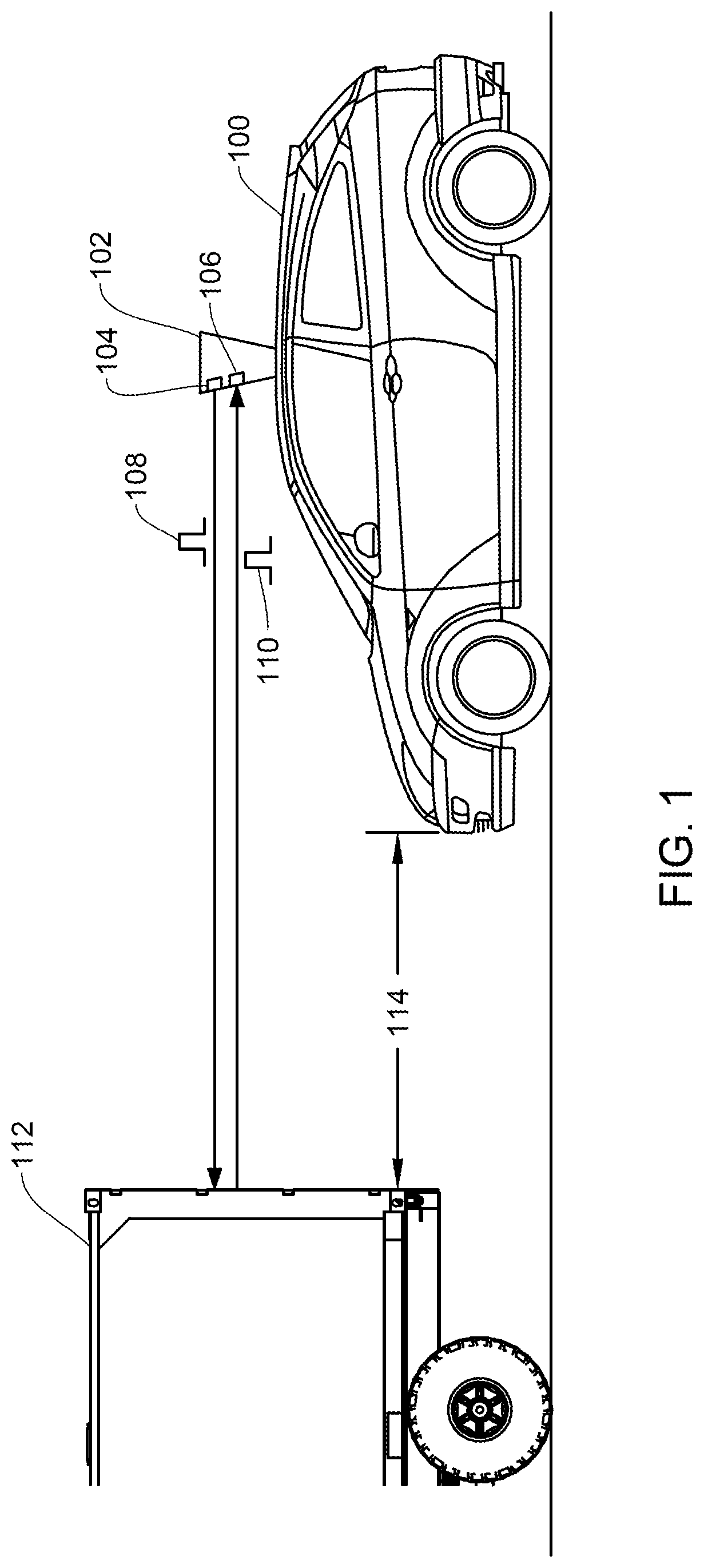
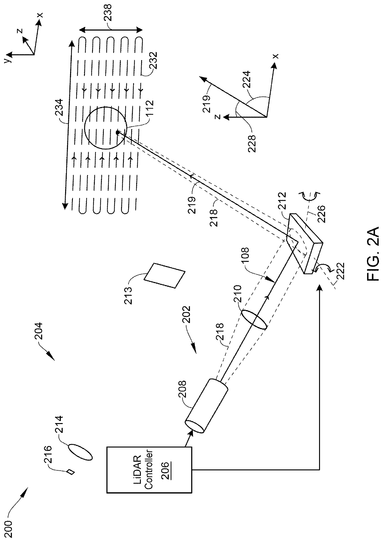
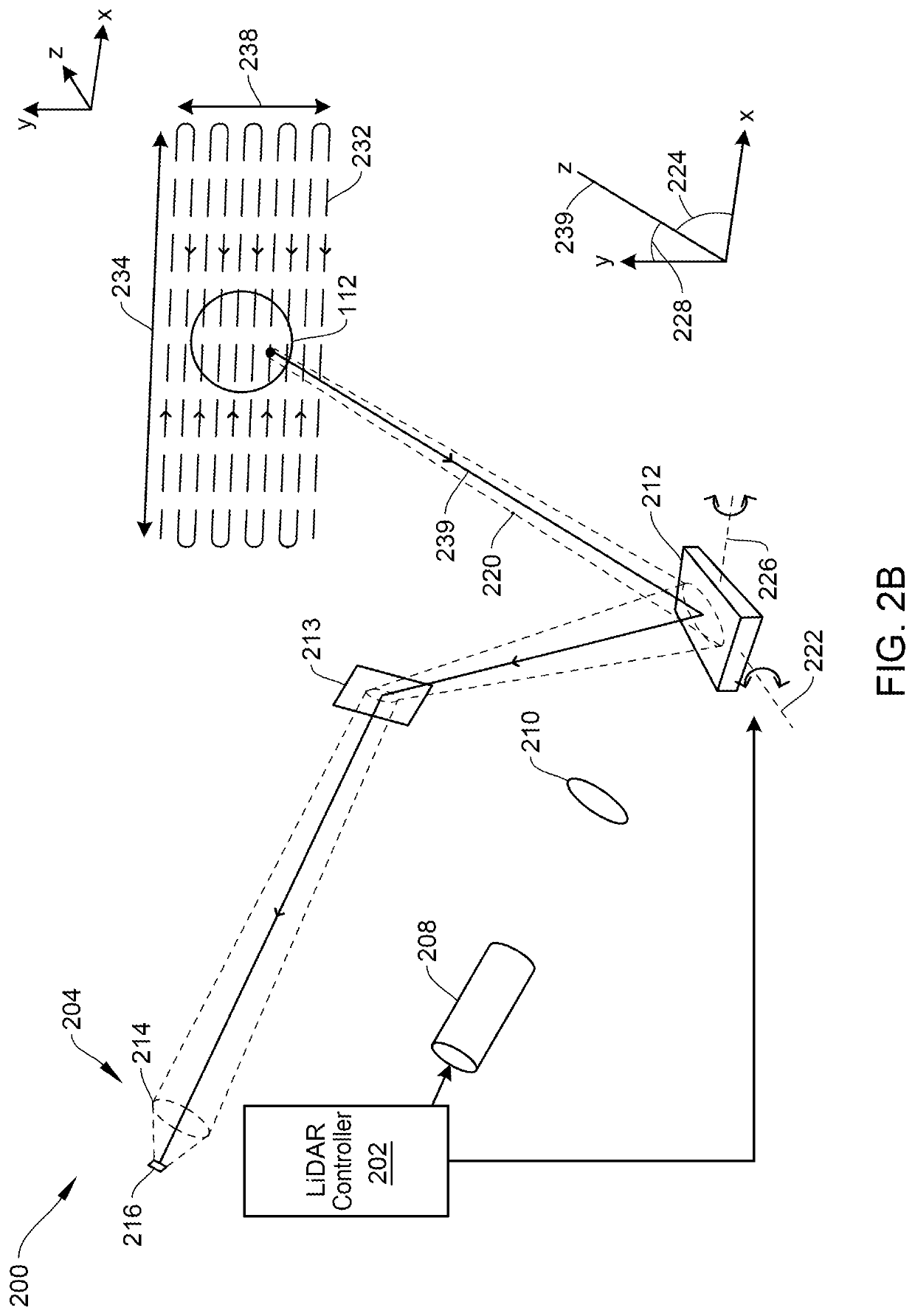
[0028]Aspects of the present disclosure relate generally to a LiDAR system, and more particularly to scanning an environment with a laser having a controlled wavelength.

[0029]In the following description, various examples of passive thermal management of laser structures are described. For purposes of explanation, specific configurations and details are set forth in order to provide a thorough understanding of the embodiments. However, it will be apparent to one skilled in the art that certain embodiments may be practiced or implemented without every detail disclosed. Furthermore, well-known features may be omitted or simplified in order to prevent any obfuscation of the novel features described herein.

[0030]Semiconductor lasers in a LiDAR system are pulsed at high frequencies to scan an environment in a short time. They need to be pulsed at sufficient power to allow the reflected pulses to be detected. The high power and frequencies heat the semiconductor laser, and over time the h...


PUM

PropertyMeasurementUnit
diameteraaaaaaaaaa
sizeaaaaaaaaaa
sizeaaaaaaaaaa

Abstract

A laser package is mounted on the printed circuit board. At least one thermal via extends through the printed circuit board, coupled to the laser package. A thermal bridge is coupled to the at least one thermal via on the bottom of the printed circuit board. A thermal paste connects the thermal bridge to a conductive ground plane on the bottom of the printed circuit board, and to a mechanical housing.

Description

BACKGROUND OF THE INVENTION[0001]Unless otherwise indicated herein, the materials described in this section are not prior art to the claims in this application and are not admitted to be prior art by inclusion in this section. In particular, disparate technologies are discussed that it would not be obvious to discuss together absent the teachings of the present invention.[0002]Modern vehicles are often equipped with sensors designed to detect objects and landscape features around the vehicle in real-time to enable technologies such as lane change assistance, collision avoidance, and autonomous driving. Some commonly used sensors include image sensors (e.g., infrared or visible light cameras), acoustic sensors (e.g., ultrasonic parking sensors), radio detection and ranging (RADAR) sensors, magnetometers (e.g., passive sensing of large ferrous objects, such as trucks, cars, or rail cars), and light detection and ranging (LiDAR) sensors.[0003]A LiDAR system typically uses a light sourc...

Claims


Application Information

Patent Timeline
Patent Type & Authority Applications(United States)
IPC IPC(8): H01S5/024H05K1/02H05K7/20H01S5/042H01S5/40H01S5/0237G01S7/481
CPCH01S5/02469H05K1/0206H05K7/20445H05K3/423H01S5/4025H01S5/0237G01S7/4815H01S5/042H01S5/0232H01S5/02315H05K1/181H05K3/0061H05K1/0209H05K2201/10121G01S17/931H05K3/34H05K2201/09563H01S5/02476H01S5/0216
Inventor YEH, YU-CHINGLU, YUEWANG, YOUMIN
Owner BEIJING VOYAGER TECH CO LTD
Why Eureka
Try Eureka