Optical disc mold having diamond-like carbonaceous layer and a molding method using the same

Inactive Publication Date: 2005-06-30
TECHNOS CO LTD
View PDF1 Cites 11 Cited by
  • Summary
  • Abstract
  • Description
  • Claims
  • Application Information

AI Technical Summary

Benefits of technology

[0016] In the present invention, upon forming a diamond-like carbonaceous layer on the stamper-holding surface which forms a part of the molding cavity surface of the optical disc mold, a predetermined surface roughness is introduced to the stamper-holding surface, thereby forming irregularity on the surface of the diamond-like carbonaceous layer. By introducing the irregularity, an air layer is formed between the back side of the stamper and the diamond-like carbonaceous layer, which functions as a heat insulator between the back side of the stamper and the stamper-holding surface, enhancing the heat-retaining property of the stamper, thereby shortening the c

Problems solved by technology

However, in order to raise the temperature of the cooled cavity surface and the stamper to or above the predetermined temperature it is required either to raise the temperature of the molten resin to be injected or to lengthen the contact period of time with the molten resin, resulting in problems of a time period for one injection molding (cycle time) being long and a productivity (shortening of the cycle time and number of injection shots per unit time) being low.
However, although the stamper having on its back surface a heat insulating layer such as ceramics, bismuth, polyimide, polyamide-imide, or the like can reduce the cycle time for

Method used


Image

  • Optical disc mold having diamond-like carbonaceous layer and a molding method using the same
  • Optical disc mold having diamond-like carbonaceous layer and a molding method using the same

Examples


Example

Example 1

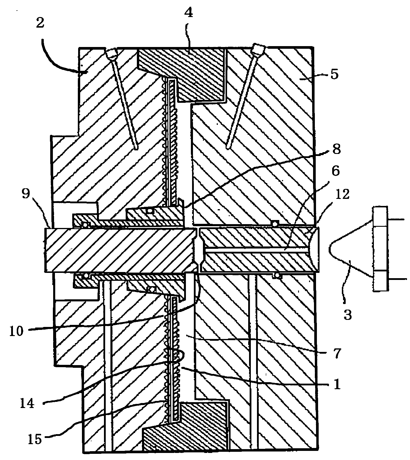
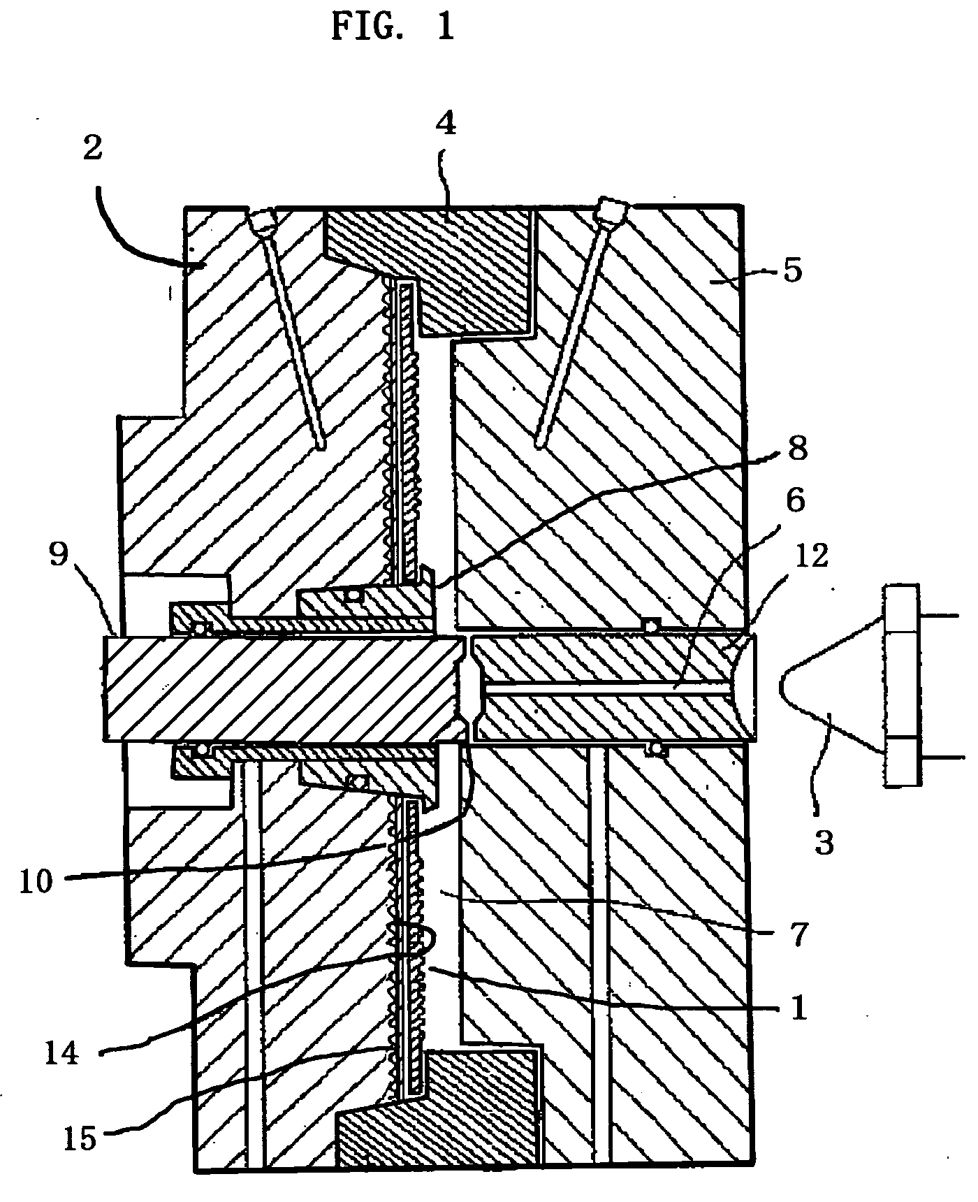
[0048] The cavity surface of the steel mold holding the stamper was subjected to mirror polishing, and the surface was subjected to scratch-brush finish in such a degree that the surface roughness Ra became approximately 1,000 Å and P-V approximately 10,000 Å. On the resultant surface, an SiC layer having a thickness of 0.5 mm was formed by flame spraying, and a diamond-like carbonaceous layer having a thickness of 1.5 μm was formed thereon. It should be noted that the diamond-like carbonaceous layer was formed by a self-bias RF plasma CVD method, under the following conditions: material gas: C2H4 (0.017 Pa.m3.s−1), electric source: RF, operating pressure: 66.5 Pa, input power: 500 W, layer-forming rate: 100 nm / min. The composition of the layer was CH0.21, and the resultant carbon layer was a diamond-like carbonaceous layer.

Example

Example 2

[0049] The cavity surface of the steel mold holding the stamper was subjected to mirror polishing, and the surface was subjected to shot peening in such manner that the surface roughness Ra became approximately 1,000 Å and P-V approximately 10,000 Å. On the resultant surface, a diamond-like carbonaceous layer having a thickness of 1.5 μm was formed. It should be noted that the diamond-like carbonaceous layer was formed by substantially the same procedure as in Example 1.

Example

Comparative Example 1

[0050] The cavity surface of the mold holding the stamper was subjected to mirror polishing, and then to scratch-brush finish in such manner that the surface roughness Ra became approximately 1,000 Å and P-V about 10,000 Å. The resultant mold was used in this Comparative Example.


PUM

PropertyMeasurementUnit
Compositionaaaaaaaaaa
Surface roughnessaaaaaaaaaa

Abstract

In order to shorten the cycle time of the molding operation, the present invention provides a mold for molding optical discs wherein irregularity having a controlled surface roughness is formed on a stamper-holding surface in a molding cavity of a mold in such degree that said irregularity is not transferred to the stamper surface, and a diamond-like carbonaceous layer is integrally formed on said surface. A method for molding optical discs comprising steps of mounting a stamper having an information pattern surface onto a stamper holding surface in a molding cavity of a mold according to the present invention and injecting a molten resin material into the cavity.

Description

TECHNICAL FIELD [0001] The present invention relates to a mold for producing optical discs using a stamper (master molding plate) and a method of producing optical discs using the mold. In particular, the present invention relates to a mold for producing optical discs with shortened cycle time and a method of producing the optical discs using the mold. BACKGROUND OF THE INVENTION PRIOR ART [0002] Optical discs are generally produced using the injection molding method. A molding cavity is formed between opposing surfaces of a fixed mold half and a movable mold half and a stamper having an information pattern on a surface in the form of pits or other irregularity according to information is mounted on a holding surface of one of the fixed and movable mold halves, a molten resin is injected into the cavity, and the mold is cooled to solidify the resin so that optical discs having an information pattern transferred from the stamper are produced. [0003] With such mold and stamper, it is ...

Claims


Application Information

Patent Timeline
IPC IPC(8): B29C33/38B29C33/56B29C45/26B29C45/37B29L17/00G11B7/26
CPCB29C33/56B29C45/2632B29K2907/04B29C2045/264B29C45/37G11B7/26
Inventor ISHIKAWA, MAKOTO
Owner TECHNOS CO LTD
Why Eureka
Try Eureka