Directional electromagnetic wave resistivity apparatus and method

a resistivity apparatus and electromagnetic wave technology, applied in the field of well logging, can solve the problems of drilling operators, inability to accurately depict the numerous segments of the borehole, and the response of these instruments generally cannot resolve the azimuthal variations in the conductivity of the formations surrounding the instruments, so as to improve the accuracy of measurements

Active Publication Date: 2005-06-30
SCHLUMBERGER TECH CORP
View PDF45 Cites 233 Cited by
  • Summary
  • Abstract
  • Description
  • Claims
  • Application Information

AI Technical Summary

Benefits of technology

[0038] In one aspect, the present invention provides a novel on-the-fly data processing technique to extract signals from the azimuthal variation of the directional measurement that are relevant for formation characterization and geosteering use. Instead of placing logging data into azimuthal bins and then determining the values associated with up and down directions as is done in conventional imaging and proposed by others, the present invention takes advantage of the simplicity of the physics of the logging response. More particularly, the relevant boundary, aniso...

Problems solved by technology

This is not, however, an accurate depiction of all the numerous segments that make up a borehole particularly when the borehole has been directionally-drilled as described below.
Layering of the formations, however, may be such that the pay zone does not lie along a predictable trajectory at geographic positions distant from the surface location of the borehole.
This presents a problem to the drilling operator, who must correct the borehole trajectory to maintain the selected position in the pay zone.
Conventional propagation-type instruments are capable of resolving axial and lateral (radial) variations in conductivity of the formations surrounding the instrument, but the response of these instruments generally cannot resolve azimuthal variations in the conductivity of the formations surrounding the instrument.
Furthermore, such instruments are unable to sense anisotropy in vertical wells.
The second is the low resistivity pay in laminated formations where accurate identification and characterization of hydrocarbon reserves is not possible without knowing the resistivity anisotropy.
However, this patent reference does not provide any details as to how the azimuthal resistivity can be obtained, nor does it describe any further boundary detection/characterization techniques required for quantitative geosteering decision-making.
No technique, however, is ...

Method used


Image

  • Directional electromagnetic wave resistivity apparatus and method
  • Directional electromagnetic wave resistivity apparatus and method
  • Directional electromagnetic wave resistivity apparatus and method

Examples


Embodiment Construction

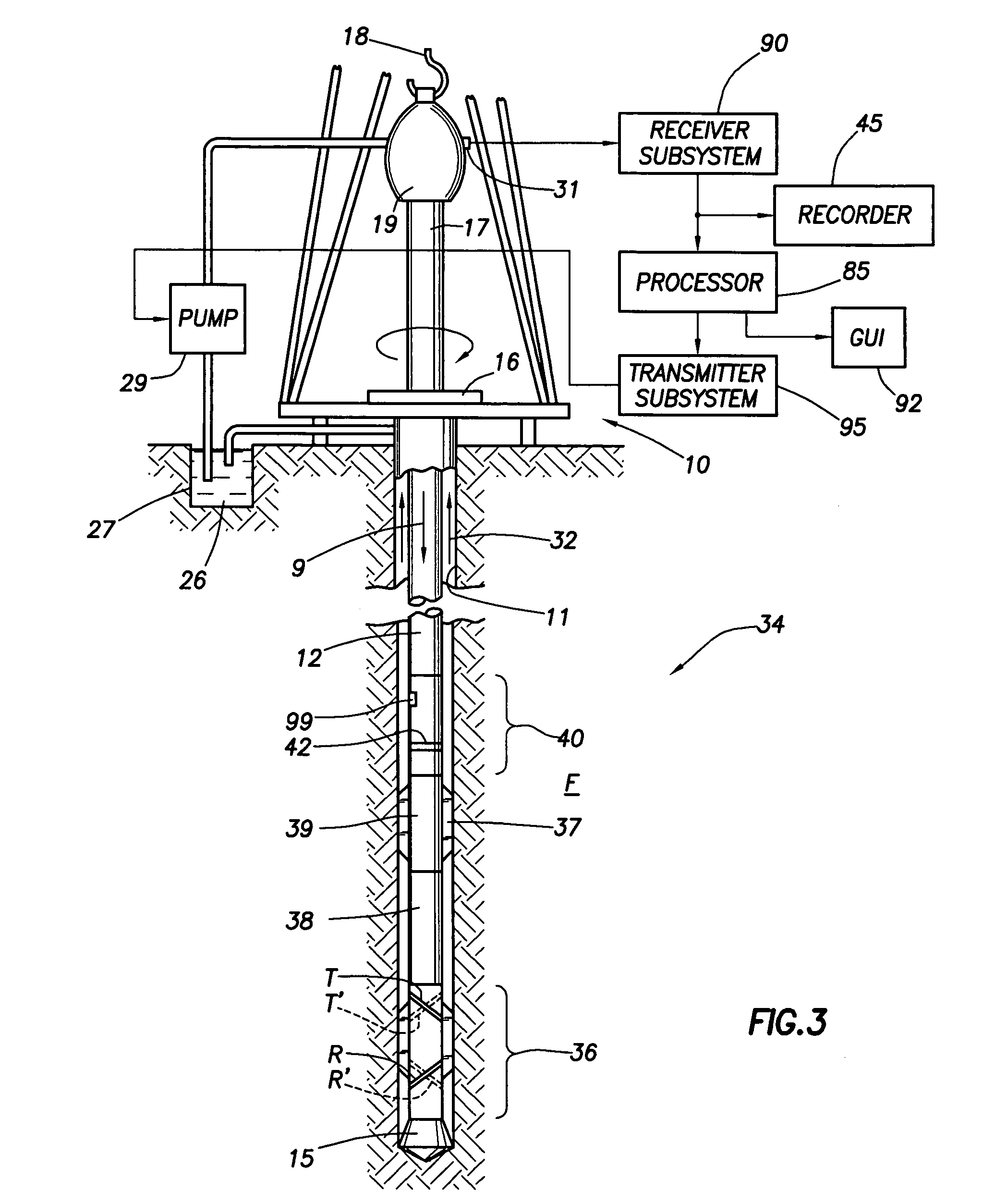
[0089]FIG. 3 illustrates a conventional drilling rig and drill string in which the present invention can be utilized to advantage. A land-based platform and derrick assembly 10 are positioned over a wellbore 11 penetrating a subsurface formation F. In the illustrated embodiment, the wellbore 11 is formed by rotary drilling in a manner that is well known. Those of ordinary skill in the art given the benefit of this disclosure will appreciate, however, that the present invention also finds application in directional drilling applications as well as rotary drilling, and is not limited to land-based rigs.

[0090] A drill string 12 is suspended within the wellbore 11 and includes a drill bit 15 at its lower end. The drill string 12 is rotated by a rotary table 16, energized by means not shown, which engages a kelly 17 at the upper end of the drill string. The drill string 12 is suspended from a hook 18, attached to a traveling block (also not shown), through the kelly 17 and a rotary swiv...


PUM


Abstract

A novel on-the-fly data processing technique is useful for extracting signals from the azimuthal variation of the directional measurements acquired by a logging tool within a borehole. The relevant boundary, anisotropy and fracture signals are extracted from the formation response through fitting of the azimuthal variation of the measured voltages to some sinusoidal functions. The orientation of the bedding is also obtained as a result. The extracted directional signals are useful for obtaining boundary distances and making geosteering decisions. Two techniques involving inversion and cross-plotting may be employed, depending on the nature of the boundary. A Graphical User Interface (GUI) is part of a system to facilitate flexible definition of inversion objectives, for improving the inversion results, and for visualization of the formation model as well as inversion measurements.

Description

CROSS REFERENCE TO RELATED APPLICATIONS [0001] This application claims the priority from U.S. Provisional Application No. 60 / 472,686 filed on May 22, 2003. This Provisional Application is incorporated by reference in its entirety.BACKGROUND OF INVENTION [0002] 1. Field of the Invention [0003] The invention relates generally to the field of well logging. More particularly, the invention relates to improved techniques in which instruments equipped with antenna systems having transverse or tilted magnetic dipole representations are used for electromagnetic measurements of subsurface formations and for placing wells with respect to geological boundaries in a reservoir. The invention has general application in the well logging art, but is particularly useful in logging-while-drilling operation. [0004] 2. Background of the Related Art [0005] Various well logging techniques are known in the field of hydrocarbon exploration and production. These techniques typically use instruments or tools...

Claims


Application Information

Patent Timeline
IPC IPC(8): G01V3/28G01V3/30
CPCG01V3/30G01V3/28
Inventor LI, QIMINGCHOU, LAWRENCEOMERAGIC, DZEVATYANG, LIBODUMONT, ALAINHU, LINGYUN
Owner SCHLUMBERGER TECH CORP
Why Eureka
Try Eureka