Ink-jet printing apparatus

a printing apparatus and inkjet technology, applied in the field of inkjet printing apparatus, can solve the problems of reducing the service life of the panel, wasting time and manpower, and affecting the quality of the printed material, so as to improve the flexibility, save the time for changing the material, and increase the throughput

Inactive Publication Date: 2005-06-30
RITDISPLAY
View PDF3 Cites 48 Cited by
  • Summary
  • Abstract
  • Description
  • Claims
  • Application Information

AI Technical Summary

Benefits of technology

[0019] As mentioned above, the ink-jet printing apparatus of the invention has proper arrangements as required. Comparing with the conventional art, the invention can change the number of the ink-jet printing device (ink-jet printing mechanism) and the positions and number of other devices (mechanisms) according to different situations. Thus, the adjustment of the apparatus has better flexibility. For example, when the throughput of the current apparatus is insufficient, the additional ink-jet print chambers (ink-jet print mechanisms) can be installed on the delivering chamber. This can increase the throughput without ordering another apparatus for larger throughput. In addition, when one ink-jet printing device is malfunction, other ink-jet print devices can keep working. Moreover, the organic material is printed in the assigned ink-jet print chamber (ink-jet print mechanism), so time for changing the material can be saved and the pollution of the different organic materials can be prevented. Furthermore, the manually moving is unnecessary in the ink-jet print processes of the invention, so not only the time cost for the manual operation can be saved, but also the organic electroluminescent panel can be prevented from the air, which results in the dark spots. Therefore, the lifetime and reliability of the panel can be assured. In addition, since ink-jet printing apparatus of the invention an automatic and integrated mass production apparatus, so that the throughput can be increased and the yield can be greatly increased.

Problems solved by technology

In the previously mentioned processes, however, the manually moving not only wastes time and manpower, but also leads to the exposure of the organic electroluminescent display panel with air during the moving, which results in a shortened lifetime of the panel.
In addition, the loaded organic materials pollute each other since the different organic materials may be loaded in the same ink-jet head.
Moreover, it wastes time for loading the different organic materials.

Method used


Image

  • Ink-jet printing apparatus
  • Ink-jet printing apparatus
  • Ink-jet printing apparatus

Examples


second embodiment

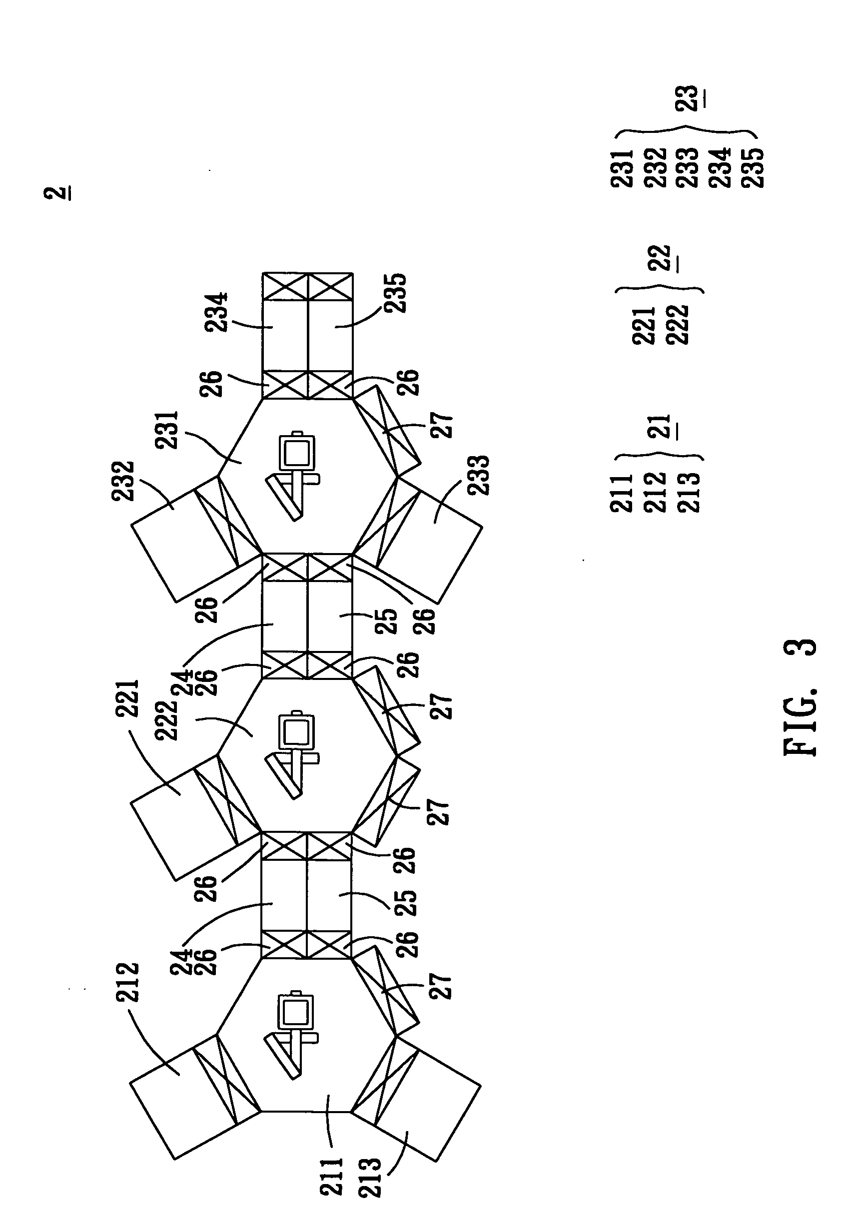
[0043] With reference to FIG. 3, an ink-jet printing apparatus 2 according to the second embodiment of the invention, which is for printing at least one organic material on a substrate, comprises a loading device 21, at least one ink-jet printing device 22, an unloading device 23, a plurality of heat treatment process devices 24 and a plurality of cooling devices 25. In the embodiment, the loading device 21 comprises a first delivering chamber 211 and a loading chamber 212 connecting to the first delivering chamber 211. The ink-jet printing device 22 comprises at least one first ink-jet printing chamber 221 and a second delivering chamber 222 connecting to the first ink-jet printing chamber 221. The second delivering chamber 222 connects to the first delivering chamber 211. The unloading device 23 comprises a third delivering chamber 231 and an unloading chamber 232 connecting to the third delivering chamber 231. The third delivering chamber 231 connects to the second delivering cha...

third embodiment

[0054] With reference to FIG. 4, except for that there are two ink-jet printing devices 22 in the embodiment, other elements are the same to those of the second embodiment. The features and functions of the individual element are the same to those of the second embodiment described previously, so the detailed descriptions are omitted here for concise purpose.

[0055] In addition, one of the second delivering chambers 222 of the embodiment has irregular shaped configuration structure.

[0056] In the present embodiment, when one of the ink-jet printing devices 22 is malfunctioned and should be stopped, the operator can continuously perform the ink-jet printing process with other ink-jet printing device 22. Thus, the malfunctioned ink-jet printing device 22 would not lead to the stop of the whole ink-jet printing apparatus 2. Of course, both the ink-jet printing devices 22 can be operated at the same time, so as to increase the total throughput.

[0057] Of course, the ink-jet printing app...

fourth embodiment

[0058] With reference to FIG. 5, an ink-jet printing apparatus 3 according to the fourth embodiment of the invention, which is for printing at least one organic material on a substrate, comprises a loading device 31, a plurality of ink-jet printing devices 32, an unloading device 33, a plurality of heat treatment process devices 34 and a plurality of cooling devices 35. The loading device 31 comprises a first delivering chamber 311 and a loading chamber 312 connecting to the first delivering chamber 311. The ink-jet printing device 32 comprises at least one first ink-jet printing chamber 321 and a second delivering chamber 322 connecting to the first ink-jet printing chamber 321. The second delivering chambers 322 connect to one another. The unloading device 33 comprises a third delivering chamber 331 and an unloading chamber 332 connecting to the third delivering chamber 331. One of the second delivering chambers 322 connects to the third delivering chamber 331, and one of the seco...


PUM


Abstract

An ink-jet printing apparatus for printing at least one organic material on a substrate comprises a delivering chamber, a loading mechanism, at least one ink-jet printing mechanism, a heat treatment process mechanism and an unloading mechanism. In this case, the delivering chamber has a delivering unit, which carries the substrate from the loading mechanism and carries the substrate to the unloading mechanism. The ink-jet printing mechanism connects to the delivering chamber and prints the organic material on the substrate. The heat treatment process mechanism connects to the delivering chamber and heats the substrate on which the organic material is formed. The unloading mechanism connects with the delivering chamber.

Description

BACKGROUND OF THE INVENTION [0001] 1. Field of Invention [0002] The invention relates to an ink-jet printing apparatus and, in particular, to an ink-jet printing apparatus applied for manufacturing organic light-emitting displays (OLED). [0003] 2. Related Art [0004] The flat-panel displays have been developed based on the trend towards high brightness, planar and thinner structures, and power saving. Accordingly, the organic electroluminescent display panel is one of the most potential products in optoelectronics industries. The organic electroluminescent display panel uses the self-emitting feature of organic functional materials to perform display purposes. According to the molecular weight of the organic functional materials used in organic electroluminescent display panel, it could be distinguished into small molecule OLED (SM-OLED) panel and polymer light-emitting display (PLED) panel. [0005] As shown in FIG. 1, the conventional organic electroluminescent display panel 6 compri...

Claims


Application Information

Patent Timeline
Patent Type & Authority Applications(United States)
IPC IPC(8): B41J3/407H01L51/00H01L51/40H01L51/56
CPCB41J3/407H01L51/56H01L51/0005H10K71/135H10K71/00
Inventor CHANG, YIHCHENG, TUNG-SHENGYEH, PEI-CHUAN
Owner RITDISPLAY
Why Eureka
Try Eureka