
Two stage injection molding machine having pressure sensor device

a pressure sensor and injection molding machine technology, applied in the direction of auxillary shaping apparatus, manufacturing tools, food shaping, etc., can solve the problems of large limitation of high precision injection, inability to accurately and thoroughly transmit force through the load cell, and lack of feedback signal required for compensating injection force, etc., to achieve high precision injection molding quality and simple structural design

Active Publication Date: 2005-06-30
IND TECH RES INST
View PDF4 Cites 3 Cited by
  • Summary
  • Abstract
  • Description
  • Claims
  • Application Information

AI Technical Summary

Benefits of technology

[0016] The pressure sensor device has a simple structural design to be applied to the two-stage injection molding machine without occurrence of conventional drawbacks such as distorted detection for the injection force and the friction force, and free of problems such as signal distortion and delayed response during the detecting process, so as to achieve the high precision injection molding quality, while thoroughly resolving conventional problems.

Problems solved by technology

However, the typical injection molding machine adopts a servomotor that merely implements a feedback control in terms of speed and position, without function for detecting pressure values during the injection, packing, and metering processes or function for implementing pressure feedback control, posing a huge limitation for the high precision injection.
However, for such conventional improvement involving an overly complicated mechanism design, the force is not correctly and thoroughly transmitted through the loadcell 40.
Yet, according to the injection rod in the above mentioned patent disclosure, the injection force and friction force sensed by the loadcell 40 are all distorted, leading to a lack of feedback signal required for compensating the injection force.
Consequently, it is difficult to achieve control of the injection pressure, packing pressure, and metering back pressure required for high speed precision injection molding.

Method used


Image

  • Two stage injection molding machine having pressure sensor device
  • Two stage injection molding machine having pressure sensor device
  • Two stage injection molding machine having pressure sensor device

Examples


first embodiment

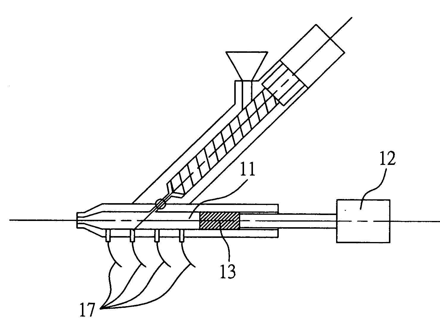
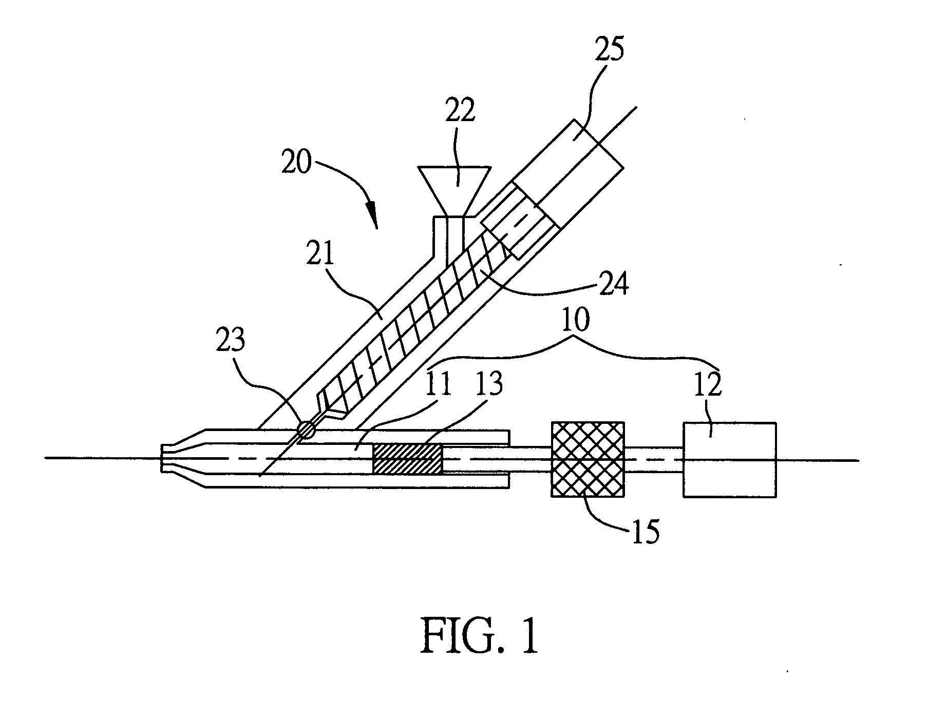
[0024]FIG. 1 illustrates a two-stage injection molding machine having a pressure sensor device according to the The injection molding machine comprises an injection part 10 having an injection cylinder 11, a driving unit 12, and an injection plunger 13, and a feeder metering part 20 formed slantwise with an angle on the injection part 10. The feeder metering part 20 allows a plastic material to be fed into the injection cylinder 11 of the injection part 10 before the material is injected out via the injection plunger 13 pushed by the driving unit 12, such as a driver. The invention is also characterized by having a loadcell 15 placed between the driving unit 12 and the injection plunger 13, so that the loadcell 15 is located along an output axis between the driving unit 12 and the injection plunger 13 to connect to both the driving unit 12 and the injection plunger 13. As a result, pressures generated in the injection cylinder 11 during the processes of feeder metering, injection, ...

second embodiment

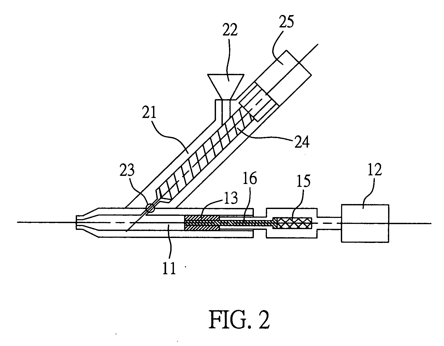
[0028]FIG. 2 illustrates the present invention. The loadcell 15 is installed behind the axis of the injection rod 13, while a pressure sensor rod 16 is installed between the loadcell 15 and the injection rod 13, so that the pressure sensor rod 16 extends into the injection rod 13 to detect the injection force and molten plastic pressure in order to implement an instant feedback control.

[0029] Similarly, the plastic beads are poured into the feeder cylinder 21 via the feeder hopper 22 in the present embodiment. The plastic beads are mixed, melted, and metered via the feeder screw rod 24 driven by the servomotor 25. As the molten plastic is fed in the feeder cylinder 11 via the opened back valve 23, the molten plastic makes contact with the loadcell 15 via the pressure sensor rod 16 installed on the injection axis, so that the loadcell 15 senses the molten plastic pressure via the pressure sensing rod 16 that is pushed by the molten plastic pressure. And as the pressure is converted v...

third embodiment

[0030] Moreover, the pressure sensor rod 16 may also be extended to detect pressure at any section of the injection cylinder 11 illustrated in FIG. 3. For instance, the pressure sensor rod 16 may be extended to the front-end 11 a of the injection cylinder 11, and the loadcell 15 may be located in a fixation cage 19 that is fixed and connected to the driver 12 to perform the similar injection operation. As the molten plastic pressure change at the front end 11 a is constantly detected via the pressure sensor rod 16 and the loadcell 15, the multi-stage back pressure metering control mode and the speed / pressure switch mode for the injection / packing process are established, so that the feedback control is implemented to complete high precision injection molding and achieve satisfactory molding quality.


PUM

PropertyMeasurementUnit
Pressureaaaaaaaaaa

Abstract

A two-stage injection molding machine having a pressure sensor device is proposed. The two-stage injection molding machine includes an injection part having an injection cylinder, a driving unit, and an injection rod installed in the injection cylinder; a metering part for feeding plastic material to the injection cylinder of the injection part; and a loadcell installed between the injection rod and the driving unit, wherein pressures in the injection cylinder during the feed metering, injection, and packing processes are detected via the loadcell and the pressure sensor rod. As a result, an accurate pressure feedback control is implemented to achieve high precision injection molding quality. And with the two-stage injection molding machine having such a simple structural design, occurrence of signal distortion and delayed response is prevented.

Description

BACKGROUND OF THE INVENTION [0001] 1. Field of the Invention [0002] The invention relates to a two stage injection molding machine having a pressure sensor device capable of detecting pressures during injection, packing and metering processes so as to implement a feedback control for a two stage injection molding machine. [0003] 2. Description of the Related Art [0004] As demand for precision and quality of the injection molding is constantly increased, it becomes more important to control the injection speed, precision, and injection pressure for a two-stage injection molding machine used to fabricate small-scale products. However, the typical injection molding machine adopts a servomotor that merely implements a feedback control in terms of speed and position, without function for detecting pressure values during the injection, packing, and metering processes or function for implementing pressure feedback control, posing a huge limitation for the high precision injection. [0005] C...

Claims


Application Information

Patent Timeline
IPC IPC(8): B29C45/54B29C45/77
CPCB29C45/54B29C2945/76936B29C2945/76006B29C2945/76013B29C2945/76187B29C2945/76204B29C2945/76307B29C2945/76367B29C2945/76381B29C2945/76384B29C2945/76454B29C2945/76498B29C2945/76595B29C2945/76846B29C2945/76859B29C2945/76862B29C45/77
Inventor CHEN, MING-CHIFENG, WEN-HUNGTENG, MING-CHANG
Owner IND TECH RES INST
Learn More