
Manufacturing method of structural body, droplet discharging head and droplet discharging device

a manufacturing method and technology of droplets, applied in the direction of rigid containers, packaging, printing, etc., can solve the problems of difficult formation of functional units, difficult deposition of light-sensitive films during photolithography process, and disadvantages of conventional processing techniques, so as to avoid complicated processes, facilitate the formation of holes, and avoid high costs

Inactive Publication Date: 2005-06-30
SEIKO EPSON CORP
View PDF5 Cites 27 Cited by
  • Summary
  • Abstract
  • Description
  • Claims
  • Application Information

AI Technical Summary

Benefits of technology

[0007] Thus, an object of the present invention is to provide technology capable of avoiding complex processes and high costs while securing the protection of the functional unit upon forming a device including a glass substrate.
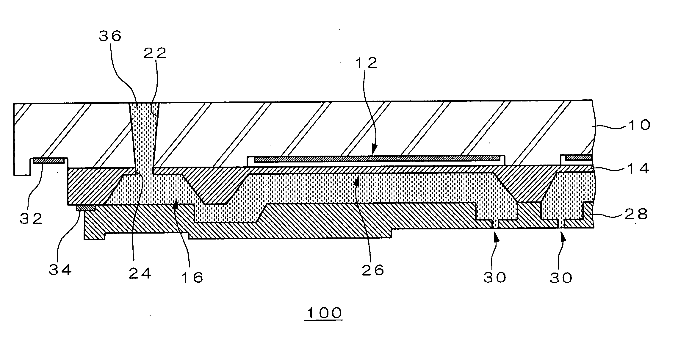
[0030] According to the foregoing manufacturing process, since the formation processing (etching processing) of the hole to the glass substrate is carried out after the functional unit formed on the glass substrate has been covered with a semiconductor substrate, it is possible to secure the protection of the functional unit without having to take any special measures, and this will enable the avoidance of complicated processes and high costs. Moreover, as a result of adopting the processing method utilizing the effect of a laser beam, deposition of the photoresist on the glass substrate is no longer required, and the formation of a hole will be facilitated thereby.

Problems solved by technology

The foregoing conventional processing techniques, however, have disadvantages as described below.
For instance, when first forming the likes of a through-hole in the glass substrate and thereafter forming a functional unit, the deposition of the photoresist (light-sensitive film) during the photolithography process will not be easy due to the existence of the through-hole or the like, and the formation of the functional unit will thereby become difficult.
Contrarily, when first forming a functional unit on the glass substrate and thereafter forming the likes of a through-hole, measures for protecting the functional unit formed first (for instance, covering the functional unit with a protective film) will become necessary prior to drilling a through-hole or the like, and this is not desirable because the process itself is not easy, and this will incur complex processes and high costs.

Method used


Image

  • Manufacturing method of structural body, droplet discharging head and droplet discharging device
  • Manufacturing method of structural body, droplet discharging head and droplet discharging device
  • Manufacturing method of structural body, droplet discharging head and droplet discharging device

Examples


Embodiment Construction

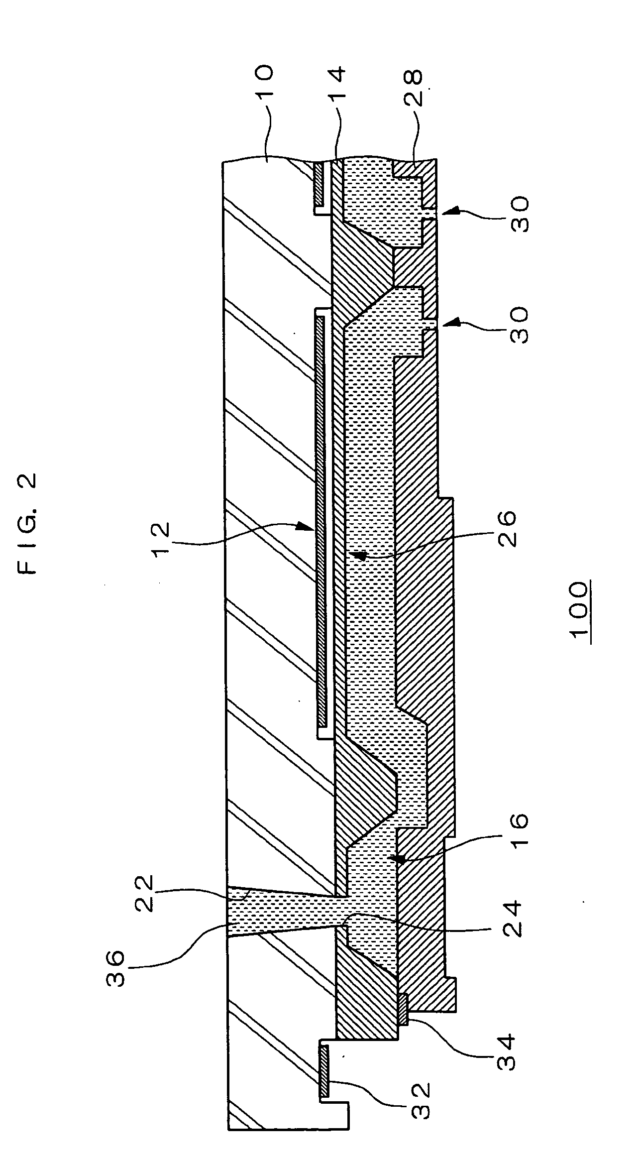
[0038] The embodiments of the present invention are now explained in detail with reference to the drawings. Below, a manufacturing method taking as an example the structural body to be employed as the structural element of a device of the droplet discharging head is explained.

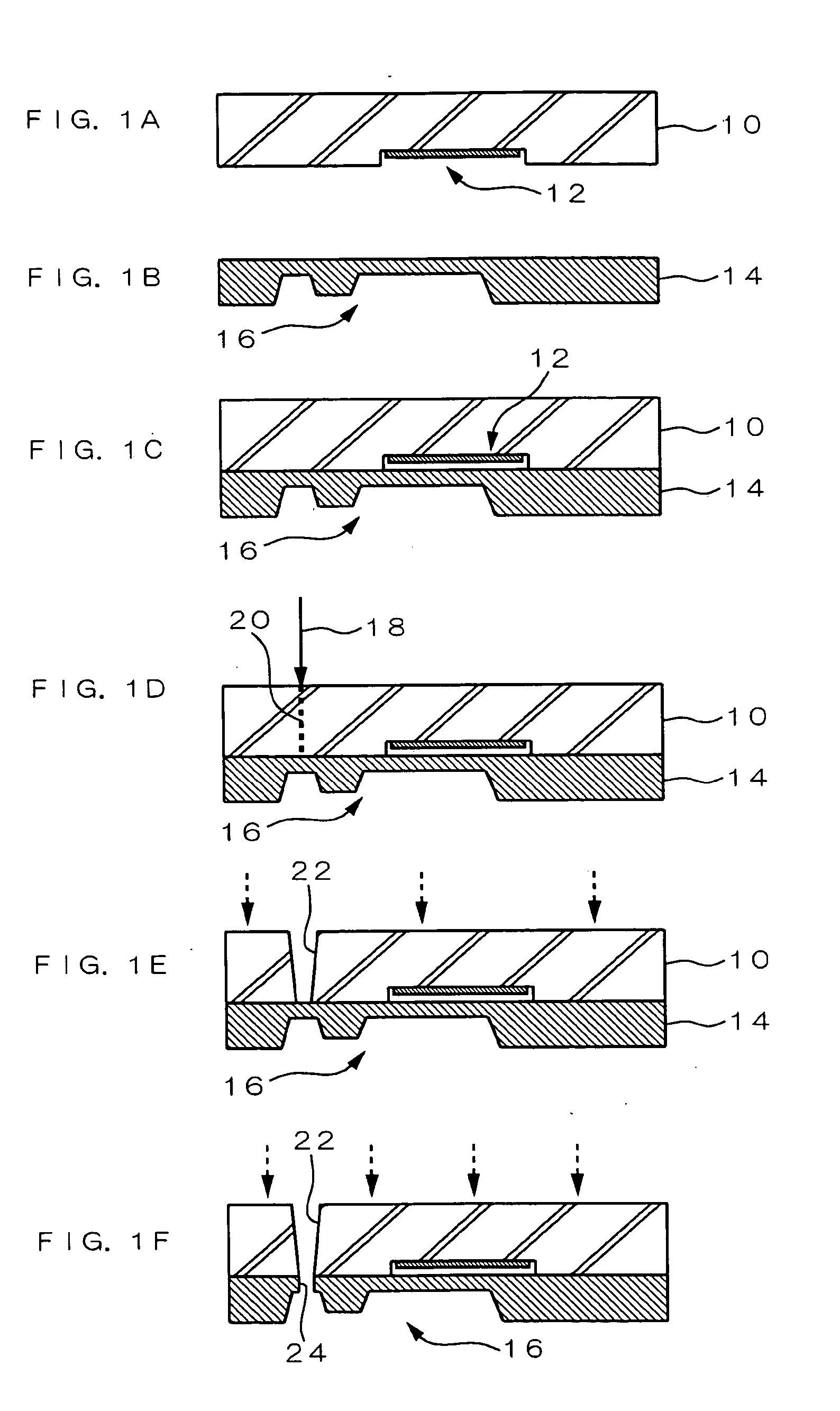
[0039]FIG. 1 is a diagram (process chart) for explaining the manufacturing method of a structural body according to an embodiment of the present invention. As show in FIG. 1(A), a glass substrate 10 is prepared, and a first functional unit 12 as the structural element of the structural body is formed on one face of the glass substrate 10.

[0040] In the present embodiment, the glass substrate 10 contains alkali ion such as sodium or lithium. More specifically, a glass substrate formed from silicate glass, borosilicate glass, aluminosilicate glass, phosphate glass or the like may be used. As a result of employing this type of glass substrate, bonding with the semiconductor substrate described later can be conduc...


PUM

PropertyMeasurementUnit
Thicknessaaaaaaaaaa
Shapeaaaaaaaaaa
Semiconductor propertiesaaaaaaaaaa

Abstract

Provided is technology capable of avoiding complex processes and high costs while securing the protection of the functional unit upon forming a device including a glass substrate. A manufacturing method of a structural body structured with a bonding body formed from a glass substrate and a semiconductor substrate, including a first step of forming a first functional unit as a structural element of the structural body on one face of the glass substrate; a second step of bonding the semiconductor substrate to one face of the glass substrate so as to cover the first functional unit; a third step of forming an affected zone extending in the thickness direction of the glass substrate by irradiating a laser beam from the other face side of the glass substrate and scanning the focal point of the laser beam in the thickness direction of the glass substrate; and a fourth step of forming a hole in the glass substrate by etching the glass substrate and removing the portion along the affected zone.

Description

BACKGROUND OF THE INVENTION [0001] 1. Field of the Invention [0002] The present invention generally relates to manufacturing technology of a structural body formed by including a glass substrate, and in particular relates to manufacturing technology preferable in manufacturing a fluidic device such as a droplet discharging head. [0003] 2. Description of the Related Art [0004] In recent years, development of devices employing MEMS (micro electro mechanical systems) technology is being conducted actively, and, for instance, this is being applied to the manufacture of various fluidic devices such as droplet discharging heads, biochips, micropumps and so on. Various researches have been conducted regarding the structure of the foregoing devices, and, for example, a structure employing a bonding body formed from a silicon substrate and a glass substrate is being used. With this kind of fluidic device, grooves, holes (recesses), through-holes and the like are formed in the silicon substra...

Claims


Application Information

Patent Timeline
IPC IPC(8): B01J4/00B32B15/04B32B17/06B81C1/00C03C15/00B41J2/16C03C23/00C03C27/02
CPCB32B15/04B32B17/06C03C15/00C03C23/0025Y10T29/4913Y10T29/49083Y10T29/49401Y10T29/49128Y10T29/49126H01L21/31111B41J2/16
Inventor KUROSAWA, RYUICHI
Owner SEIKO EPSON CORP
Learn More