This helps you quickly interpret patents by identifying the three key elements:
Problems solved by technology
Method used
Benefits of technology
Benefits of technology
[0041] It is an object of the present invention, which was devised in view of the points described above, to provide an optical amplifying device contrived to improve an optical transmission quality by compensating gain flatness even for a fluctuation in WDM signal state.
Problems solved by technology
Consequently, a gain deviation is caused, and there arises such a problem that the gain flatness is not compensated according to the prior art that does not take the change in the wavelength count or the wavelength allocation into consideration.
The non-linear phenomenon, however, appears because of being unable to follow up with a change in photoelectric field having a speed equal to or higher than this recovery time.
Method used
Image
Click on the blue label to locate the original text in one second.
Reading with bidirectional positioning of images and text.
Examples
first embodiment
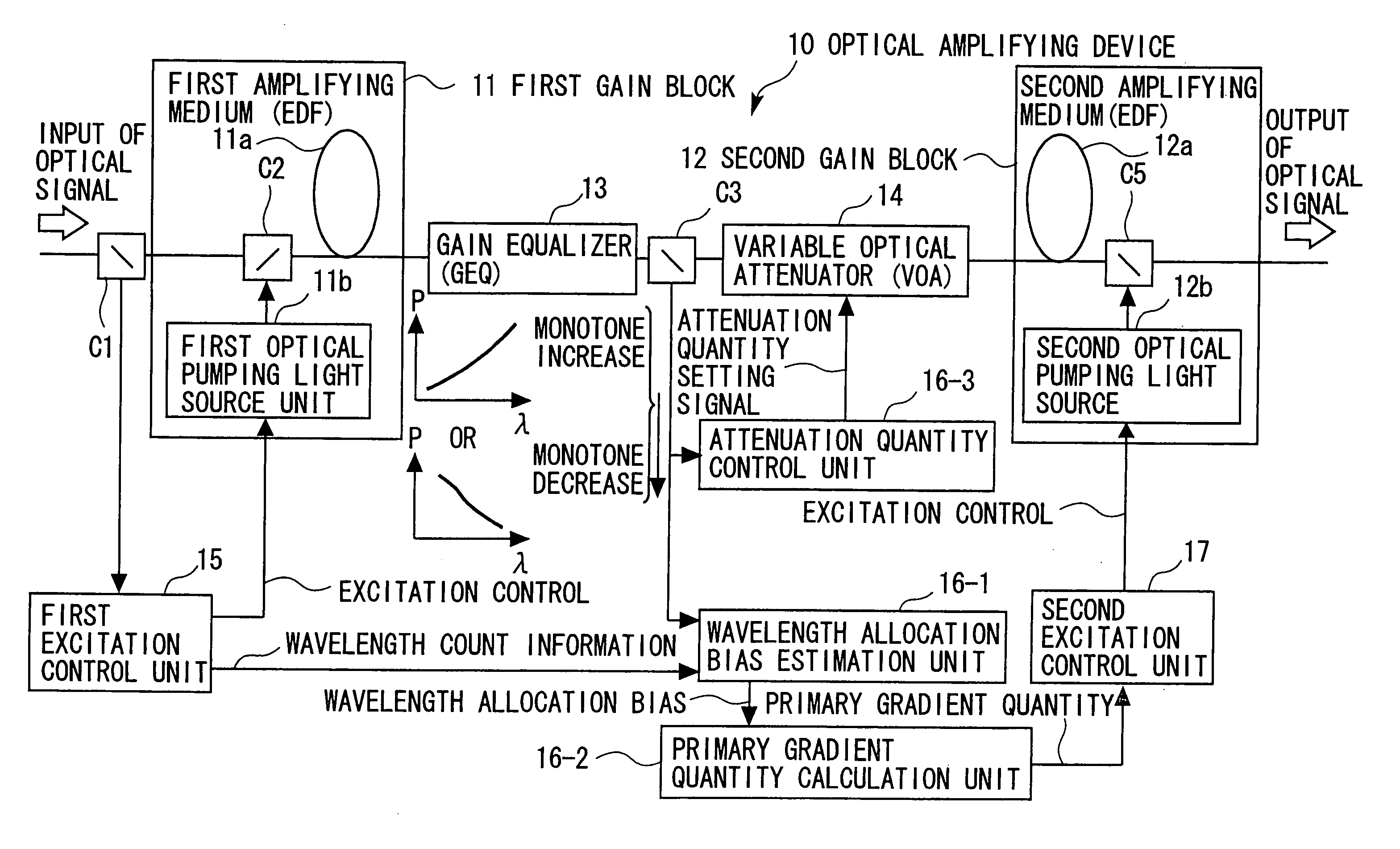
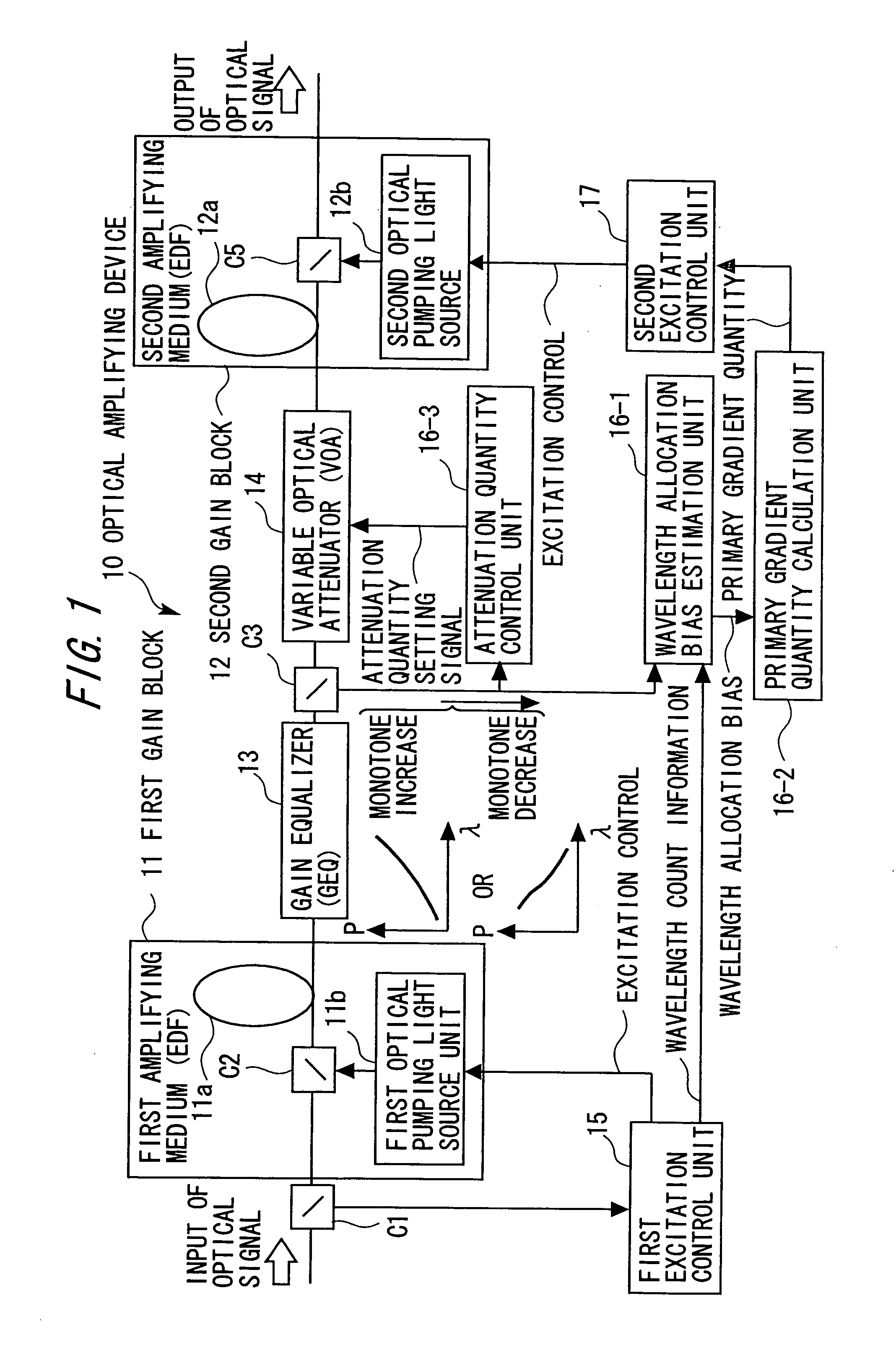
[0097] Embodiments of the present invention will hereinafter be described with reference to the drawings. FIG. 1 is a view of a principle of an optical amplifying device according to the present invention. An optical amplifying device 10 is a device for amplifying a WDM optical signal and is applied to an optical repeater in a WDM transmissionsystem.
[0098] A first gain block 11 installed on an input side of the optical amplifying device 10 is an EDFA (Erbium-Doped FiberAmplifier) constructed of a first amplifying medium 11a (which will hereinafter be termed an EDF 11a) in which an active substance such as erbium (Er3+), etc. for optical amplification is doped, a first optical pumping source unit 11b for emitting excitation light, and a multiplexer C2. The first optical pumping source unit 11b emits the excitation light via the multiplexer C2 installed on the optical input side of the EDF 11a. The optical signal is thereby amplified.
[0099] A second gain block 12 installed on an o...
second embodiment
Judgement from Magnitude of Out. 1 with PP Corresponding to Wavelength Count
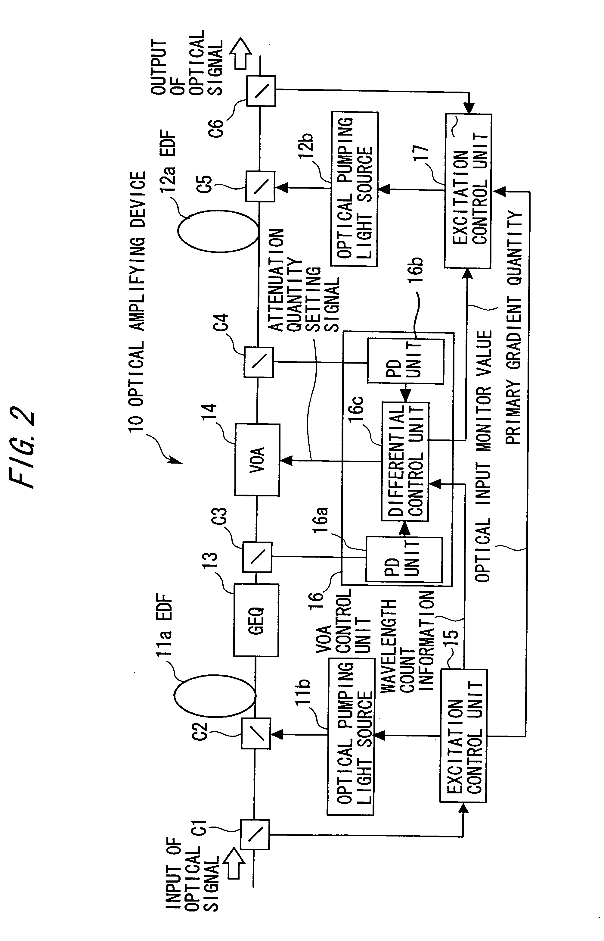
[0170]FIG. 26 is a view schematically showing a construction of the optical amplifier according to a second embodiment of the present invention. The optical amplifying device 10 is a device for amplifying the WDM optical signal and is applied to the optical repeater in the WDM transmission system.
[0171] The first gain block 11 installed on the input side of the optical amplifying device 10 is the EDFA (Erbium-Doped FiberAmplifier) constructed of the first amplifying medium 11a (which will hereinafter be termed the EDF 11a) in which the active substance such as erbium (Er3+), etc. for optical amplification is doped, the first optical pumping source unit 11b for emitting the excitation light, and the multiplexer C2.
[0172] The first optical pumping source unit 11b emits the excitation light via the multiplexer C2 installed on the optical input side of the EDF 11a. With this operation, the first gain block 1...
third embodiment
Identification Using Power of LD1 when Effecting AGC at Stage of GEQ
[0213] In the second embodiment discussed above, the wavelength equi-allocation power is compared with the power of the optical signal L13, thus recognizing the wavelength bias. According to the third embodiment, however, first excitation light power when controlling the power of the optical signal L13 to be fixed is compared with first excitation light power (reference excitation light power) when the wavelengths are equally allocated, thus recognizing a wavelength bias. Note that the configuration other than this wavelength bias recognizing method in the third embodiment is the same as the second embodiment discussed above has, and hence their repetitive explanations are omitted by marking the same components with the same numerals and symbols.
[0214]FIG. 30 is a view schematically showing a configuration of the optical amplifying device 10 in the third embodiment.
[0215] In the third embodiment, a first excitati...
PUM
Abstract
A contrivance, if a WDM signal state changes, is to improve an optical transmission quality by compensating gain flatness. A first excitation control unit sets a first optical pumpinglight source unit to emit excitation power needed to get the same amplifying operating level of a first amplifying medium as at the time of a maximum wavelength count when allocating wavelengths after a change in wavelength count at an equal interval in a wavelength range. A wavelength allocation bias estimation unit compares a present monitor value of optical power after outputting of a gainequalizer 13 with wavelength equi-allocation power associated with the recognized wavelength count, and thus estimates a wavelength allocation bias occurred as a concomitant of the change in the wavelength count. A primary gradient calculation unit obtains a primary gradient quantity defines as a gain deviation from the wavelength allocation bias. A second excitation control unit sets, in a second optical pumpinglight source unit, the excitation power needed to cancel the primary gradient quantity. An attenuation quantity control unit controls a variable optical attenuator to fix a gain by compensating an amount of change in the sum of gains.
Description
BACKGROUND OF THE INVENTION [0001] The present invention relates an optical amplifying device, and more particularly to an optical amplifying device for amplifying a WDM (Wavelength Division Multiplex) optical signal. [0002] Over the recent years, with developments of the Internet technologies, there has been a great leap in demands for information services, and a larger capacity and a more flexible network configuration are required of an optical transmission system in a backbone system. [0003] There is WDM (Wavelength Division Multiplex) as a most effective transmission technology that responds to such a system demand. The WDM is defined as a transmission method of multiplexing fluxes of light having different wavelengths and simultaneously transmitting a plurality of signals via a single optical fiber, and its commercialization is now underway as centralized in North America. [0004] On the other hand, an EDFA (Erbium-Doped FiberAmplifier) is given as a key component for actualiz...
Claims
Application Information
Patent Timeline
Application Date:The date an application was filed.
Publication Date:The date a patent or application was officially published.
First Publication Date:The earliest publication date of a patent with the same application number.
Issue Date:Publication date of the patent grant document.
PCT Entry Date:The Entry date of PCT National Phase.
Estimated Expiry Date:The statutory expiry date of a patent right according to the Patent Law, and it is the longest term of protection that the patent right can achieve without the termination of the patent right due to other reasons(Term extension factor has been taken into account ).
Invalid Date:Actual expiry date is based on effective date or publication date of legal transaction data of invalid patent.

