Gravity dependent pedicle screw tap hole guide and data processing device
a technology of pedicle screws which is applied in the field of gravity-dependent pedicle screw tap hole guides and data processing devices, can solve the problems of limiting this range of motion, screw body or its threads breaking through the vertebral cortex, and being in danger of striking the surrounding nerve roots, etc., and avoiding the effect of affecting the normal operation
- Summary
- Abstract
- Description
- Claims
- Application Information
AI Technical Summary
Benefits of technology
Problems solved by technology
Method used
Image
Examples
second embodiment
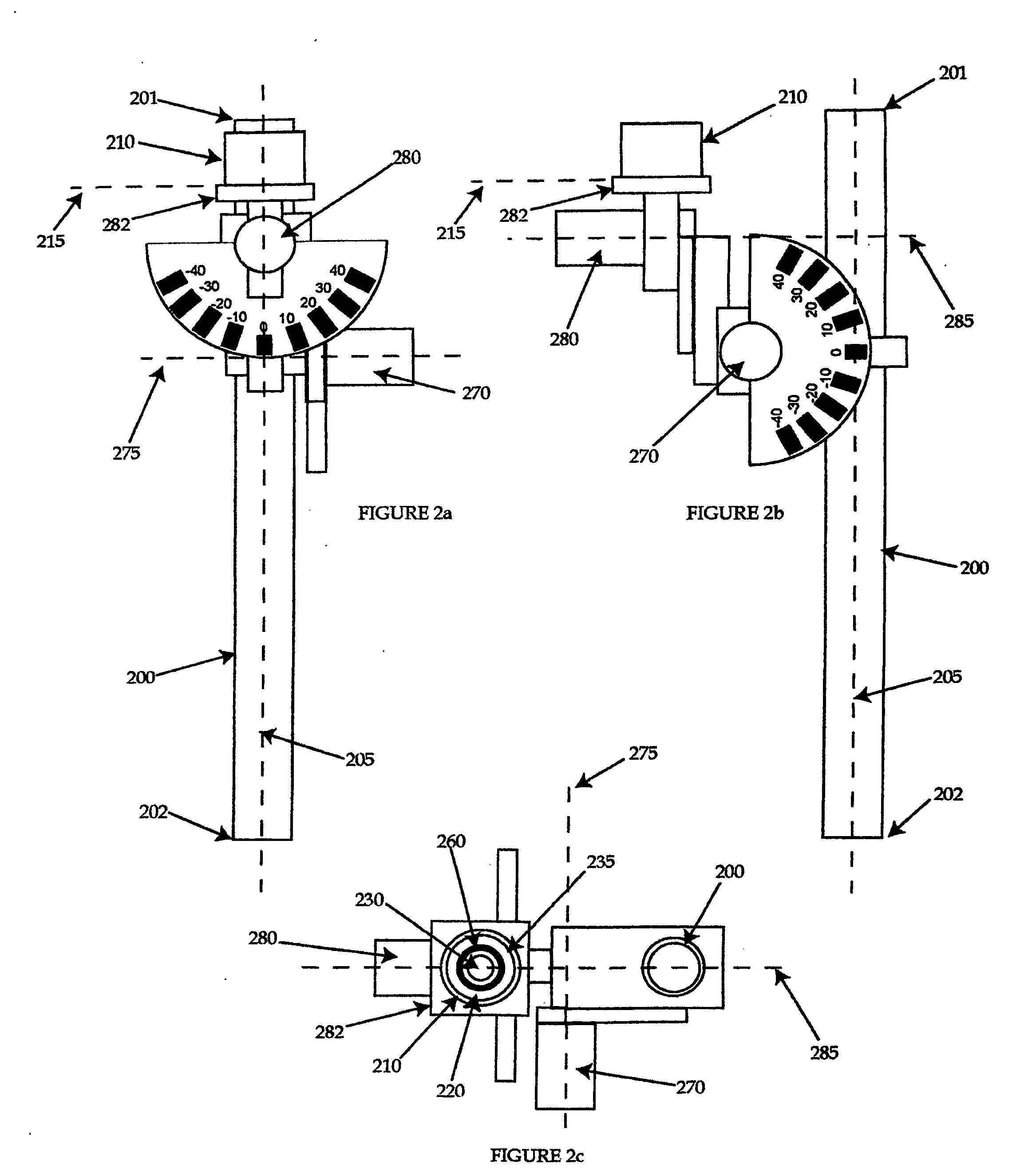
[0052] Operation of this embodiment proceeds as indicated with regard to the second embodiment, with the accelerometer 410 indicating when the accelerometer 410 is oriented level (and thus, if the rotatable mountings 470, 480 have been rotated to match the cephalad-caudad declination and medial angulation of the pedicle, that the shaft 400 is at the desired angulation).
[0053] Referring now to FIGS. 5a-c, yet another embodiment of a gravity dependent pedicle screw tap hole guide of the present invention is illustrated. The guide in this embodiment is similar structurally and functionally to the third embodiment described above, with a difference in that the accelerometer is connected to a data processing device or system, which difference will be described in detail below. More particularly, the illustrated embodiment is similar in all other respects to the third embodiment described above, and as such similar components and features are numbered similarly, except in the 500s rather ...
third embodiment
[0054] Operation of this embodiment proceeds similarly as indicated with regard to the third embodiment, with the accelerometer 510 determining when the shaft 500 is in the desired position, that is, when the angular difference between the longitudinal axis of the shaft 500 and the acting direction of gravity matches the cephalad-caudad declination (in the first plane) and medial angulation (in the second plane) of the pedicle. As noted above, however, in addition, the accelerometer 510 is in communication with the data processing device or system 526.
[0055] The data processing device or system 526 can be of any type known in the art, and is preferably able to do at least one of the following: (1) obtain signals received from the accelerometer 510, (2) interpret such signals, (3) determine desired data or information from such signals, (4) present such data or information to another device or to a user (using any presentation manner known in the art, for example, but not limited to,...
fourth embodiment
[0060] The accelerometer 610 is similar to the accelerometer 410 described in the fourth embodiment described above, but in this embodiment does not have a display (it should be understood that in other variations of this embodiment, the accelerometer 610 can have one or more displays of its own, and even its own data processing capability separate from the data processing device or system 626 described below). Preferably as shown, at least one input connection 622 and at least one output connection 624 allow the accelerometer 610 to communicate with a data processing device or system 626. Either or both of the input connection 622 and the output connection 624 can be accomplished by any manner and / or via any device known in the art for allowing two objects to communicate, such as, for example, a wired or wireless connection. Furthermore, it some embodiments, it may desirable for only input connection(s) or only output connection(s) to be present (i.e., in which signals and / or data ...
PUM
 Abstract
Description
Claims
Application Information
 - R&D
- Intellectual Property
- Life Sciences
- Materials
- Tech Scout
- Unparalleled Data Quality
- Higher Quality Content
- 60% Fewer Hallucinations
Browse by: Latest US Patents, China's latest patents, Technical Efficacy Thesaurus, Application Domain, Technology Topic, Popular Technical Reports.
© 2025 PatSnap. All rights reserved.Legal|Privacy policy|Modern Slavery Act Transparency Statement|Sitemap|About US| Contact US: help@patsnap.com


