Method and apparatus for producing molten iron

Inactive Publication Date: 2005-07-14
HYLSA SA DE CV
View PDF38 Cites 10 Cited by
  • Summary
  • Abstract
  • Description
  • Claims
  • Application Information

AI Technical Summary

Benefits of technology

[0018] It is a further object of the invention to provide an improved system for producing molten iron adapted for its installation in conjunction with existing direct reduction plants, in order to substitute and efficiently utilize fuels having a lower cost that natural gas and therewith produce high quality pig-ir

Problems solved by technology

Blast furnaces, however, require costly coke.
This has several drawbacks, not the least of which is that coking coal is not found throughout the world.
Thus, in many instances it must be imported at great cost to the iron producer.
Along with the cost associated with transforming coal into coke, coking plants are not considered environmentally friendly under new pollution regulations in many countries.
But to date, these processes have failed to provide an operational plant capable of producing molten iron at competitive prices when compared with blast furnaces or with combined direct reduction and electric furnace facilities.
Hot reducing gases and powdered carbon are introduced toward a molten iron bath in the melting portion of the furnace, Stift's process however requires additional heat to be provided to the hot gases besides the heat produced by the partial combustion, and the integration of the reduction shaft with the melting furnace does not allow for providing the optimal conditions for the three main processes involved, namely: reduction of ores, melting of reduced ores and production of reducing gases.
For example, since the oxidation reactions of the fuel take place inside the melting furnace, some of the reactants may react with the bed of coke and co

Method used


Image

  • Method and apparatus for producing molten iron
  • Method and apparatus for producing molten iron
  • Method and apparatus for producing molten iron

Examples


Embodiment Construction

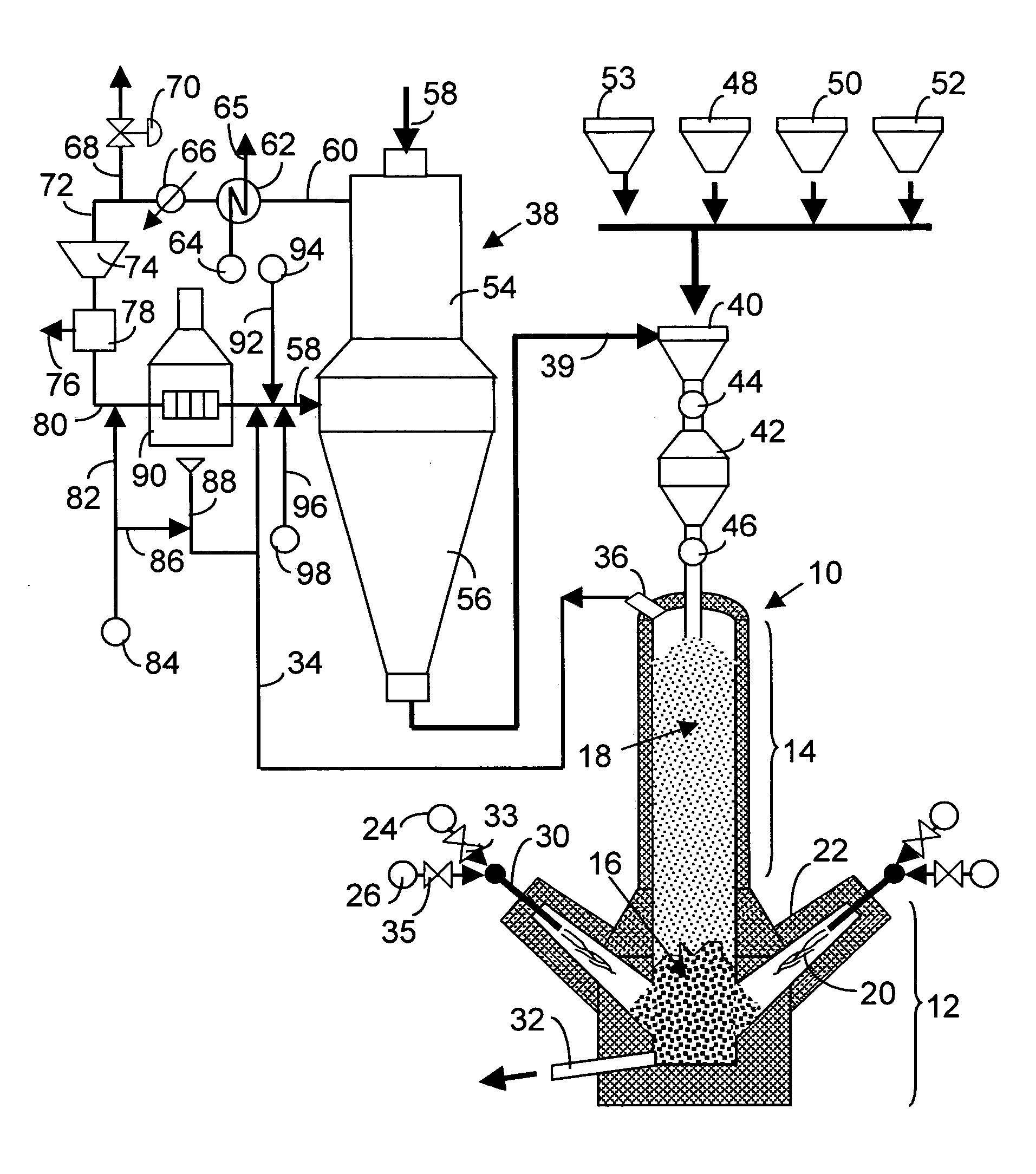
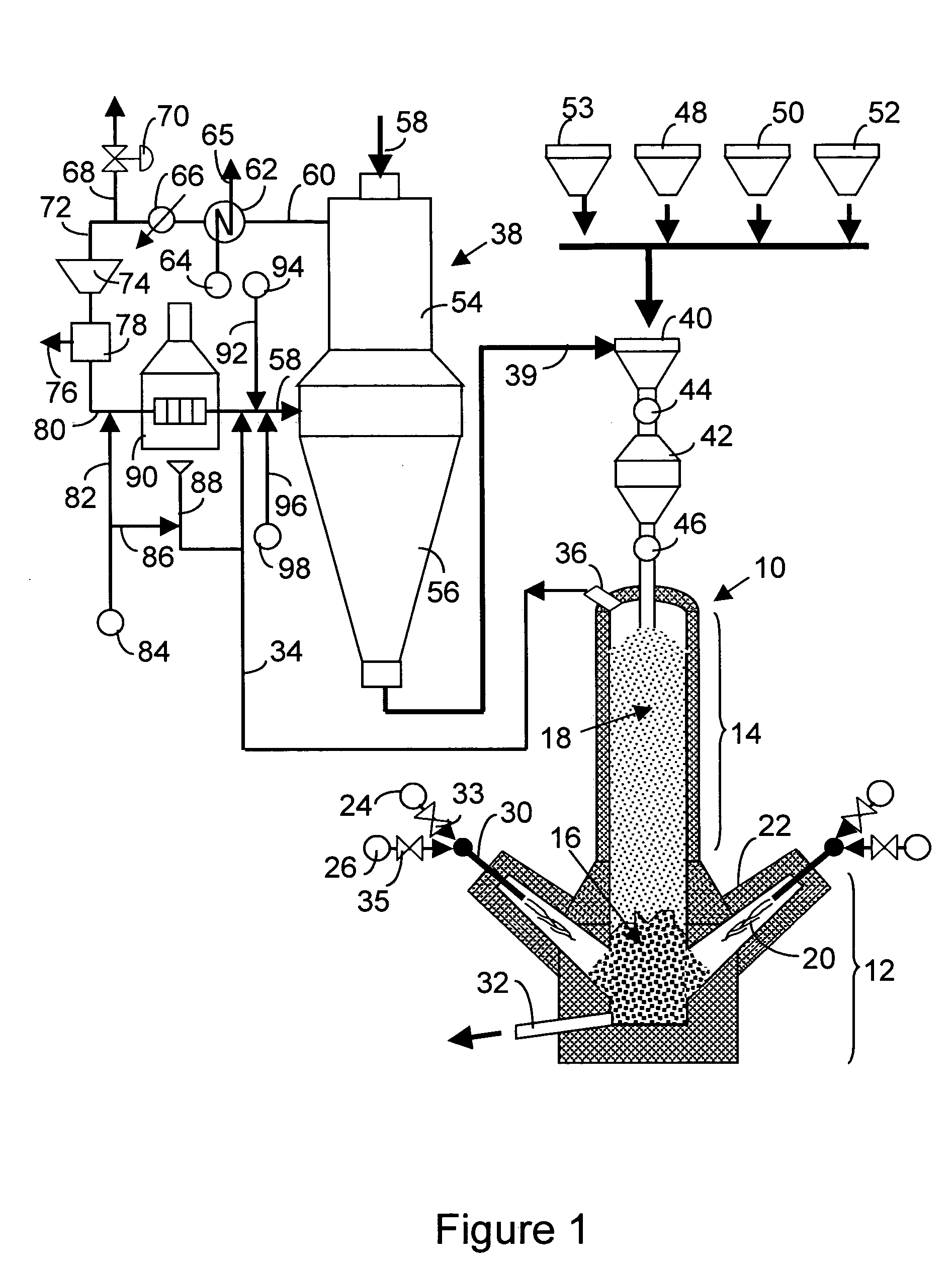
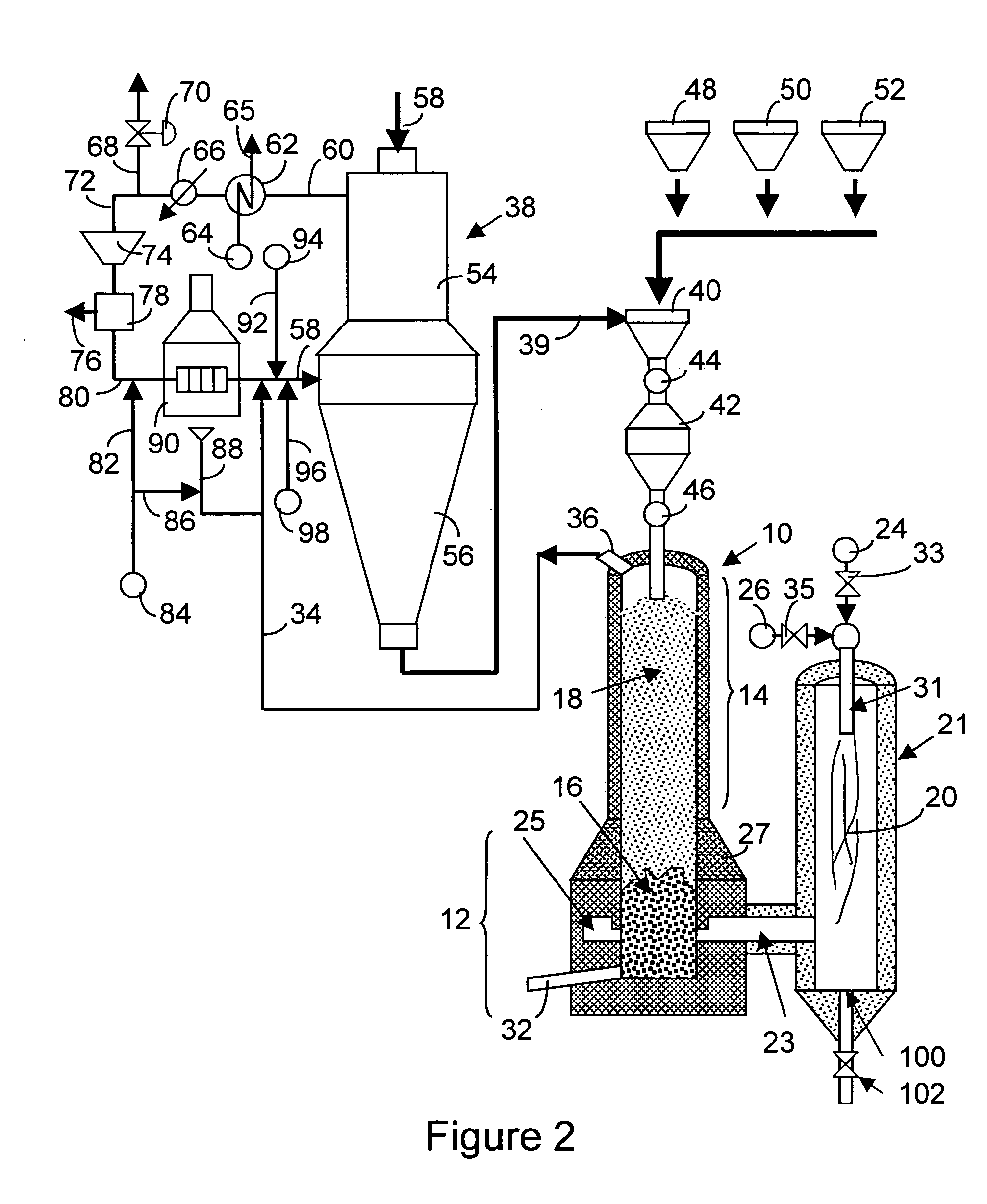
[0029] The present invention will now be described with reference to the Figures. Referring to FIG. 1, a melting furnace 10 having a crucible section 12 and a charging shaft 14 is shown. A bed of coke 16 fills a major portion of the crucible section 12 providing a porous support for a bed 18 of metallic-iron-containing particles which descend through the shaft section 14 as said iron particles melt down. The high-temperature reducing gas 20 produced in a plurality of gas generating zones 22 passes through the coke bed 16 with a composition comprising in its major part hydrogen and carbon monoxide, however, the mixture may contain some carbon dioxide and water, the classic by-products of combustion, and also some methane or other un-burnt fuel. The actual composition of the reducing gases 20 will depend on the type of fuel utilized and will be adjusted to a desired reducing potential value by reacting a fuel 24 and a free oxygen-containing gas 26. Flow rates of fuel and oxygen-gas ar...


PUM

PropertyMeasurementUnit
Temperatureaaaaaaaaaa
Lengthaaaaaaaaaa

Abstract

A system for producing molten iron from iron ores, including a direct reduction shaft furnace, a melting zone in a melting furnace having a coke bed in its lower portion and a charging and preheating chamber in its upper portion, and at least one reducing gas generation zone in communication with said melting zone.

Description

RELATED APPLICATIONS / PATENTS & INCORPORATION BY REFERENCE [0001] A claim of priority is made to U.S. Provisional Application No. 60 / 507,160, filed Sep. 30, 2003.[0002] Each of the applications and patents cited in this text, as well as each document or reference cited in each of the applications and patents (including during the prosecution of each issued patent; “application cited documents”), and each of the PCT and foreign applications or patents corresponding to and / or claiming priority from any of these applications and patents, and each of the documents cited or referenced in each of the application cited documents, are hereby expressly incorporated herein by reference. More generally, documents or references are cited in this text, either in a Reference List before the claims, or in the text itself; and, each of these documents or references (“herein-cited references”), as well as each document or reference cited in each of the herein-cited references (including any manufactu...

Claims


Application Information

Patent Timeline
IPC IPC(8): C21B13/00C21B13/02C21B13/14
CPCC21B13/002C21B13/143C21B13/02C21B2100/22C21B2100/282C21B2100/44C21B2100/64Y02P10/122Y02P10/134
Inventor VIRAMONTES-BROWN, RICARDOVILLARREAL-TREVINO, JUAN ANTONIOLOPEZ-GOMEZ, RONALD VICTOR MANUEL
Owner HYLSA SA DE CV
Why Eureka
Try Eureka