Regulated open-loop constant-power power supply

a constant-power power supply and open-loop technology, applied in the direction of electric variable regulation, process and machine control, instruments, etc., can solve the problems of inefficiency of led driver circuit, inability to operate continuously, and inability to accurately control current regulators, etc., to achieve the effect of reducing weight, cost, heat and space, and improving efficiency

Inactive Publication Date: 2005-07-14
SCHNEIKER HENRY D +1
View PDF8 Cites 53 Cited by
  • Summary
  • Abstract
  • Description
  • Claims
  • Application Information

AI Technical Summary

Benefits of technology

[0021] For example, a closed-loop type of power supply may typically utilize a sense resistor or similar apparatus for sensing an overcurrent, measuring an output current, measuring an output voltage, etc. In such a case, an eliminatio...

Problems solved by technology

However, as discussed further below, continuous mode operation is not always possible or desirable.
However, current limiting resistors cause power loss that results in inefficiency of an LED driver circuit, and current regulators may be imprecise.
In addition, constant voltage power supplies may be inappropriate for driving LEDs because of a st...

Method used


Image

  • Regulated open-loop constant-power power supply
  • Regulated open-loop constant-power power supply
  • Regulated open-loop constant-power power supply

Examples


Embodiment Construction

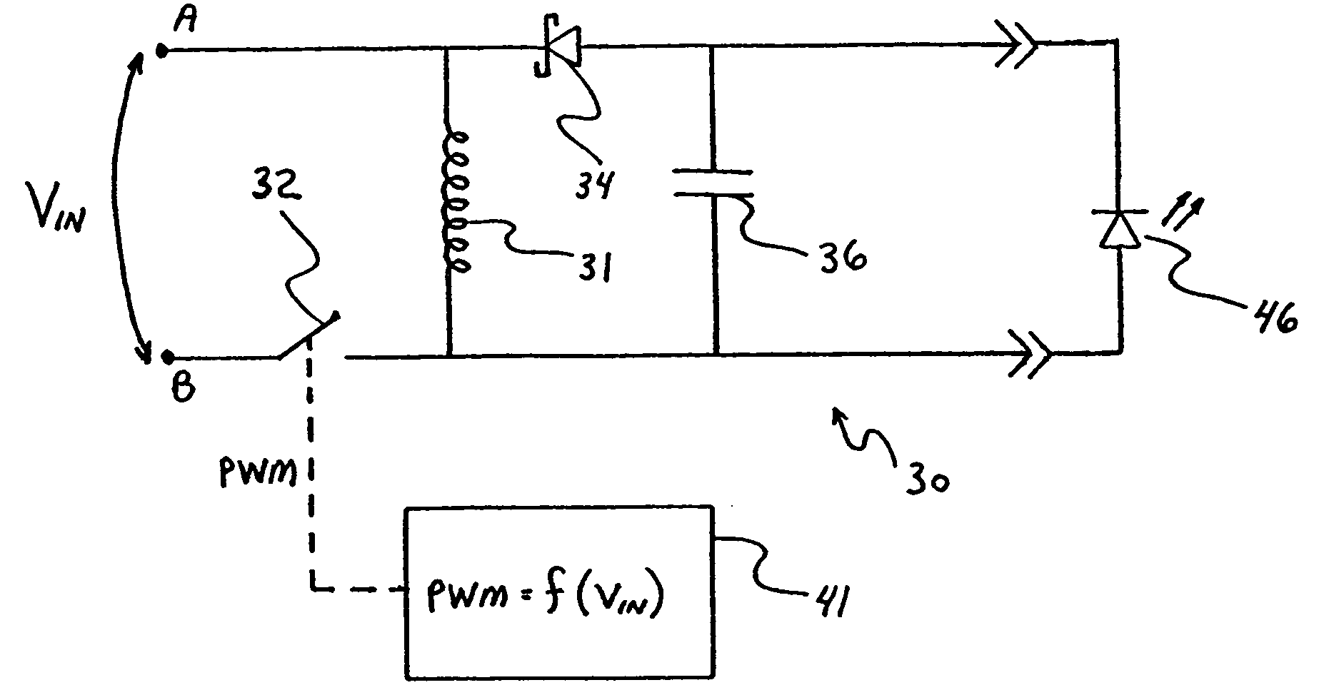
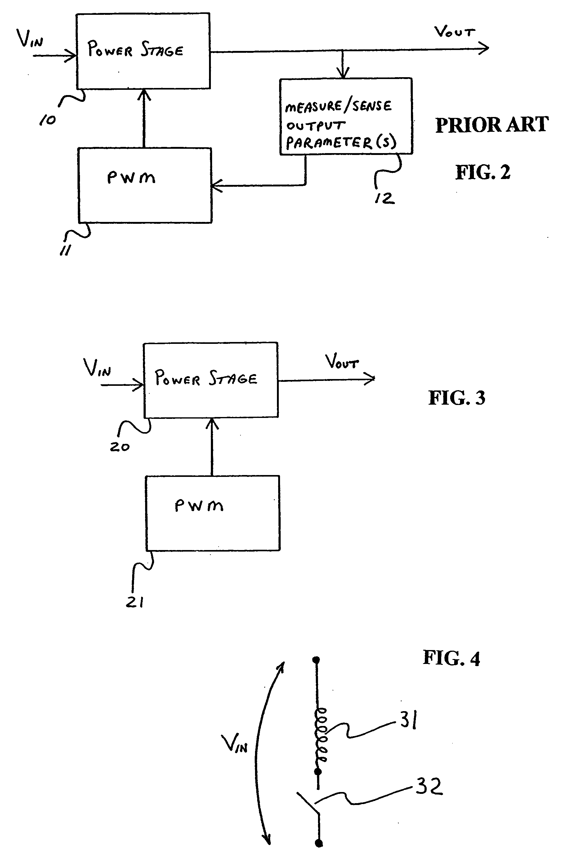
[0046] A buck-boost power stage is conventionally a part of a control loop of a buck-boost power supply. As shown in FIG. 2, such a power supply control loop includes a power stage 10, a pulse width modulator (PWM) 11, and an error amplifier 12 that detects at least one output parameter and controls the operation of the PWM 11 based on the detected output parameters. An output parameter may typically be an output current, output voltage, output power, or similar quantity. Conventional detectors for output parameters may include use of comparators, resistor configurations, dedicated sense lines, etc. In any case, a regulation of the output current or voltage conventionally relies on a feedback type control loop. In FIG. 2, an input voltage VIN is input to the power stage 10 which provides an output voltage VOUT to a load. The present inventors have determined that an open loop configuration may be used in certain applications, so that the FIG. 2 configuration is simplified.

[0047] Ac...


PUM


Abstract

A constant-power switching power supply has an inductor with an inductor current that remains in discontinuous conduction mode (DCM), where the power supply supplies and maintains constant output power to a load without measuring output parameters, by regulating charge-up time of the inductor. A method of maintaining a constant output power for a power supply being run in discontinuous conduction mode (DCM), having an inductor, includes obtaining a measured input voltage for voltage being input to the power supply, obtaining from a memory a set of values based on the measured input voltage, and driving a pulse width modulation (PWM) generator based on the set of values, the driving of the PWM generator thereby regulating a charge-up time of the inductor to correspond to the measured input voltage, whereby the regulating of the charge-up time of the inductor maintains an essentially constant power for a load.

Description

BACKGROUND [0001] 1. Technical Field [0002] The present invention is directed generally to power conversion and, more particularly, to a switching power supply and methods that provide a constant power to a load. [0003] 2. Description of the Related Art [0004] An inductive switching regulated power supply may be implemented in various configurations to convert an input voltage into an output voltage. Such power supplies may be classified by a type of topology being utilized. For example, topologies may include buck, boost, buck-boost, single-ended parallel inductor converter (SEPIC), and Cuk. Such configurations may include a switch, diode, inductor, and capacitor. A particular topology may be selected, for example, based on a transfer function desired for a given application. In general, a buck type circuit has an output voltage (Vo) less than an input voltage (Vi), a boost type circuit has a Vo greater than a Vi, and a buck-boost type circuit has a Vo that can be greater than or l...

Claims


Application Information

Patent Timeline
IPC IPC(8): G05F1/10H02M3/156
CPCH02M3/156H05B33/0815H02M2001/0022H05B45/3725H02M1/0022
Inventor SCHNEIKER, HENRY D.GRANSEE, PETER
Owner SCHNEIKER HENRY D
Why Eureka
Try Eureka