Module for radio-frequency applications

a radio frequency module and module technology, applied in the direction of printed circuit aspects, printed circuit non-printed electric components association, semiconductor/solid-state device details, etc., can solve the problems of high profile, high cost, and difficult pickup, so as to improve the resistance of saw package protruding from the module substrate to electromagnetic field noise, the effect of reducing the height of the saw packag

Inactive Publication Date: 2005-07-14
HITACHI LTD
View PDF7 Cites 44 Cited by
  • Summary
  • Abstract
  • Description
  • Claims
  • Application Information

AI Technical Summary

Benefits of technology

[0022] Grounded conductors are preferably formed on the inner layer or the rear surface of the periphery of the throughhole formed in the module substrate in which at least a section of the SAW package is mounted. The grounded conductor encloses the SAW filter to function as an electromagnetic shield for the SAW filter. The grounded conductor in this way improves the SAW fi

Problems solved by technology

However, RF modules containing SAW filters have the problem of a high profile.
This problem is caused by the fact that the height of the SAW package is 0.6 mm or more even when a low-profile (thin) SAW package sealed in resin is used and this height is large compared to the other chip components (size 0603, height 0.3 mm) and semiconductor devices that are mounted at the same time.
However, in the prior method, forming a large hole in the metal cap weakens the shield effect and has the further problem of making pickup difficult when mounting the module on the motherboard.
In the latter method, the cost becomes drastically expensive when the RF substrate is resin and when the substrate is ceramic has the problem t

Method used


Image

  • Module for radio-frequency applications
  • Module for radio-frequency applications
  • Module for radio-frequency applications

Examples


Embodiment Construction

[0036] The RF module of the present invention is described next in detail while referring to the embodiments shown in the accompanying drawings. Identical reference numerals in FIG. 1A, FIG. 1B through FIG. 6A, 6B indicate the same item or similar item.

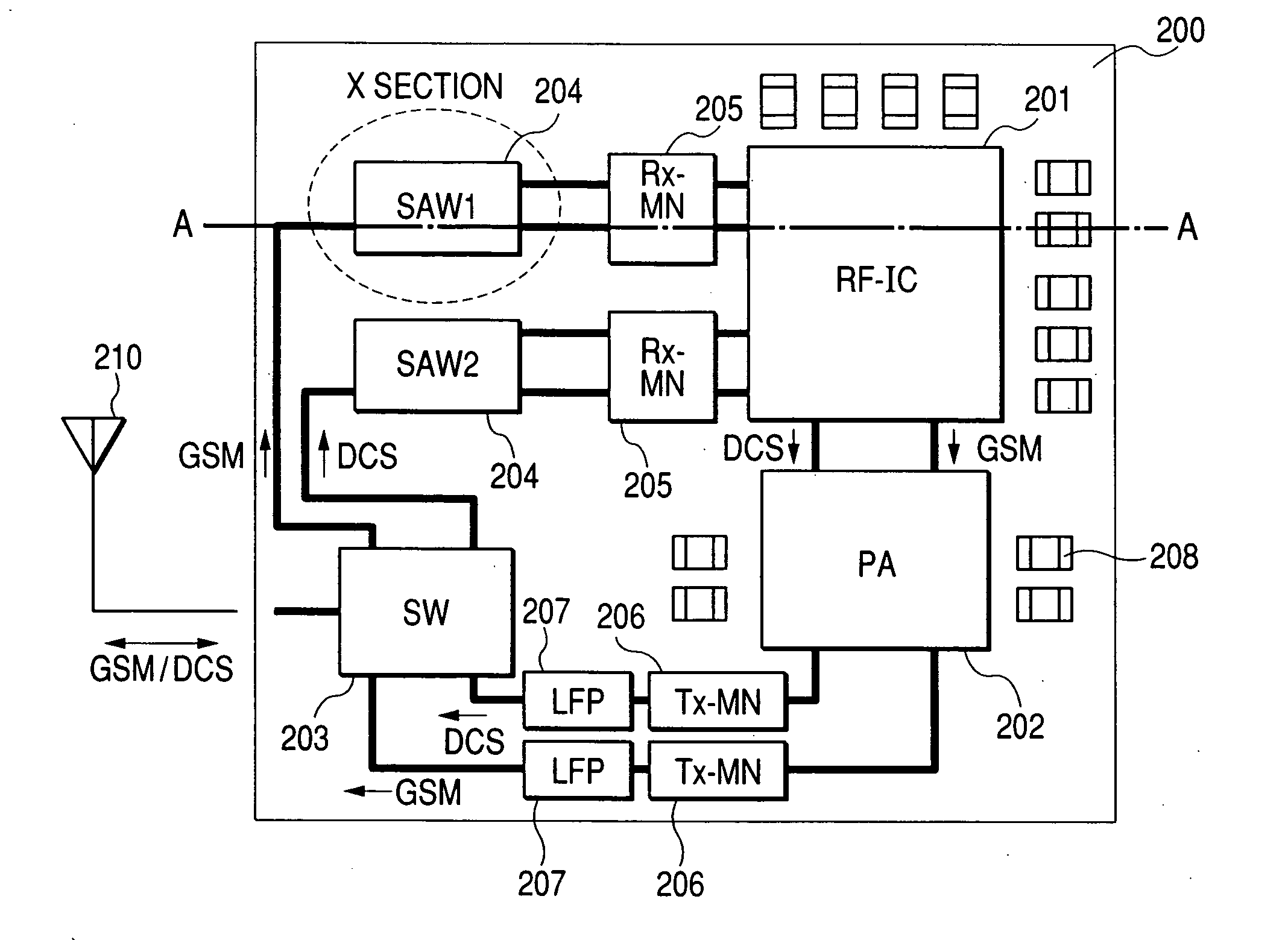
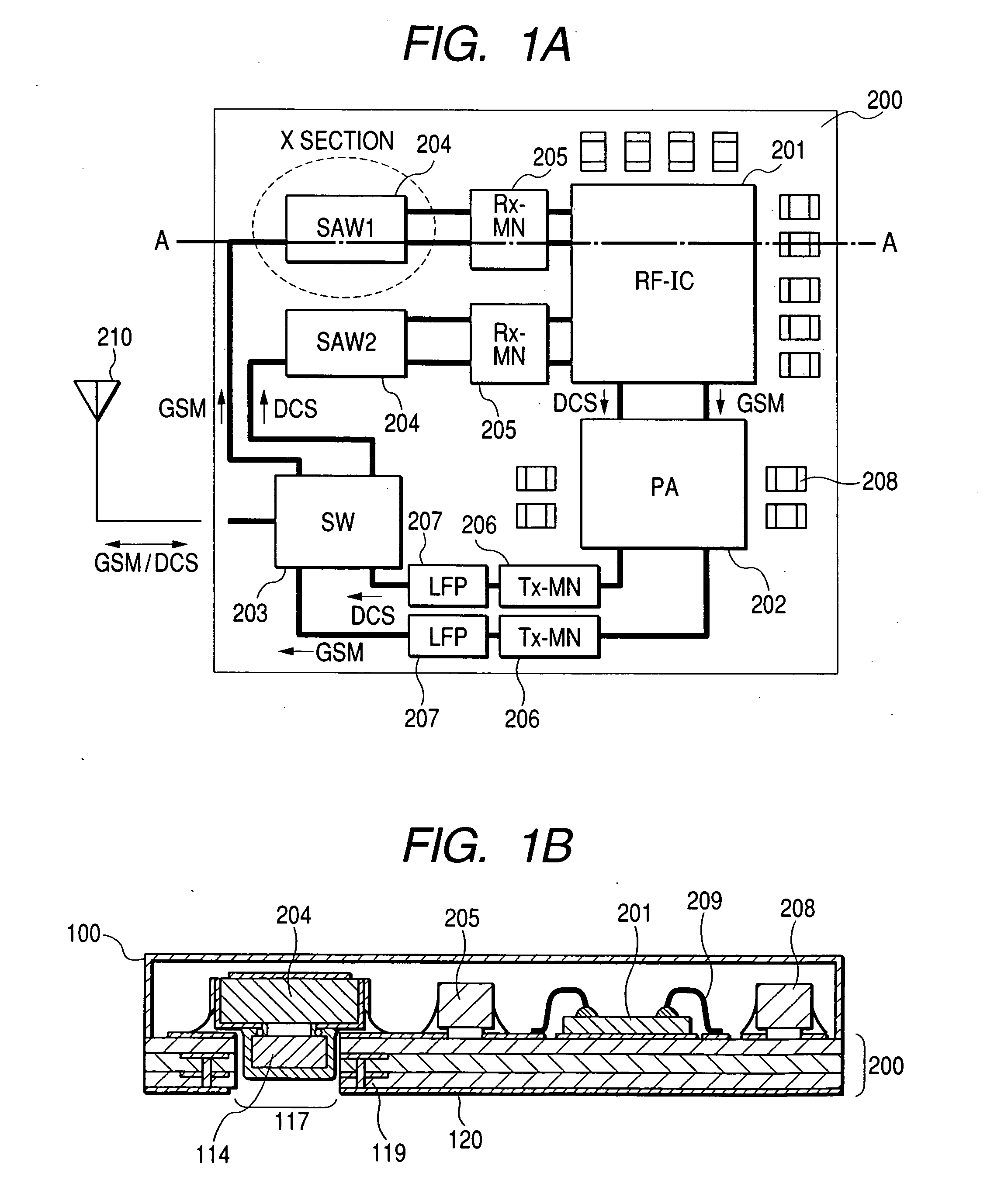
[0037] The first embodiment of the present invention is described next while referring to FIG. 1A, 1B, FIG. 2A, 2B and FIG. 3A, 3B. FIG. 1A is a block diagram of the RF module of the present invention. FIG. 1B is a cross sectional view taken along line A-A of FIG. 1A. As shown in FIG. 1A, the electronic components, RF-IC201, PA202, SW203, SAW package 204, matching circuit 205, and the chip components (capacitor, resistor, inductor) 208 for conveying the RF signal are mounted on the upper surface of the module substrate 200. The entire upper surface of the RF module is normally covered with a metal cap or sealed in a resin mold. However, these are omitted in FIG. 1A in order to describe the internal structure. Usually a large number o...


PUM


Abstract

A radio frequency module with a SAW package mounted on the substrate is provided in a low profile structure also having excellent resistance to noise or in other words, electromagnetic compatibility even when a resin-sealed SAW package is utilized. Organic laminate of at least a single layer is used as the substrate of the radio frequency module, and a throughhole is formed on that organic laminate. The resin-sealed SAW package that encloses a flip-chip mounted SAW filter is mounted so that the ceramic substrate is positioned mainly outside the throughhole, and the SAW filter is positioned mainly inside the throughhole. A grounding conductor is formed on the rear side or the inner layer in the vicinity of the throughhole.

Description

CLAIM OF PRIORITY [0001] The present invention claims priority from Japanese application JP 2004-002595 filed on Jan. 8, 2004, the content of which is hereby incorporated by reference into this application. FIELD OF THE INVENTION [0002] The present invention relates to a radio frequency module for wireless communication devices such as wireless portable terminals typified by cellular phones. BACKGROUND OF THE INVENTION [0003] In recent years, much progress has been made in making cellular phones more compact and with a lower profile. Along with this progress, many advances are also being made in making normally tall electronic components in particular such as antenna switches, power amplifier (hereafter called “PA”), and surface-acoustic-wave (hereafter called “SAW”) filters smaller (compact) and with a lower profile. [0004] On the other hand, producing the radio frequency (hereafter called, “RF”) section of a cellular terminal which is a combination of multiple electronic component...

Claims


Application Information

Patent Timeline
IPC IPC(8): H05K1/18H01L23/12H01L25/00H01L25/04H01L25/18H03H9/05H03H9/10H03H9/25H03H9/72H05K1/02H05K3/34H05K3/46
CPCH03H9/0542H03H9/0576H01L2924/3025H01L2924/19107H01L2924/19105H01L2224/48465H01L2224/48227H01L2224/48091H01L2224/73204H05K2201/10727H05K2201/10083H03H9/059H03H9/1085H03H9/72H03H9/725H05K1/0243H05K1/182H05K3/3442H01L2924/00014H01L2924/00
Inventor IDO, TATEMIOKABE, HIROSHI
Owner HITACHI LTD
Why Eureka
Try Eureka