[0011] According to one form of the present invention, there is provided a method of reducing the diameter of a sidewall of a seamless unitary metal container body having a sidewall, an endwall at one end of the sidewall, an open end at an opposite end of the sidewall, and a longitudinal axis extending between the endwall and the open end. The method involves introducing a knockout element into the container body through the open end, providing a forming die shaped to reduce the diameter of the sidewall of the container body when the open end of the container body is forced therein to produce a neck portion of reduced diameter on the container body, driving the open end of the container body into the forming die, retracting the knockout element through the neck portion as the neck portion is formed, and removing the container body from the forming die and knockout element. The method utilizes at least one linear reciprocal
prime mover arranged to create movement or force in the direction of the longitudinal axis of the container body to move the knockout element, or to force the container body into the forming die, or both.
[0013] The use of linear prime movers under computer
numerical control for manipulating thin gauge metal offers a wide variety of advantages over conventional technology and is not limited to die necking. The present invention provides a high degree of versatility in forming operations and a capability to change profile shaping and a variety of operating parameters in real time.
Cam development can be accomplished using the readily adjustable process of the present invention to derive
empirical data quickly and efficiently with programmable adjustment of variables such as motion, force and velocity.
Stroke length can be adjusted by simply dialing in the desired length
on the fly and without shutting down operations as opposed to tearing the
machine down, removing the
cam that determines thrust, retooling the
cam, replacing and testing the new
stroke to determine if it matches the intended modification and finally to determine if the modification matches the intended result on the
cam profile. A variety of forming variables and associated ratios can be customized and easily adjusted for individual operations and can be controlled independently for each stage in a multiple stage
machine. The present invention allows forming operations that require a high degree of variability and precision to be possible. It also allows machinery to be developed which may have been impractical from a development standpoint using
current technology.
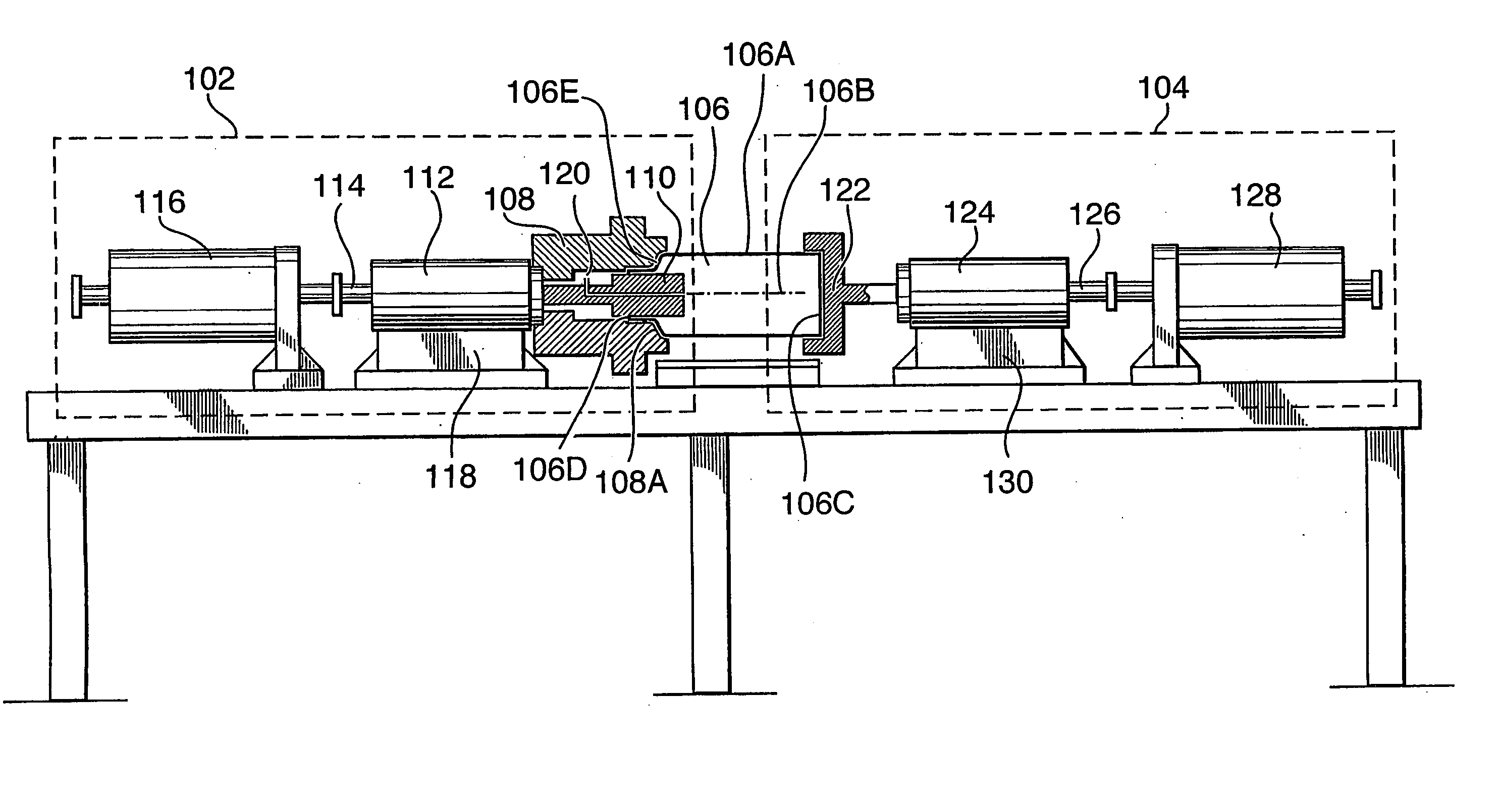
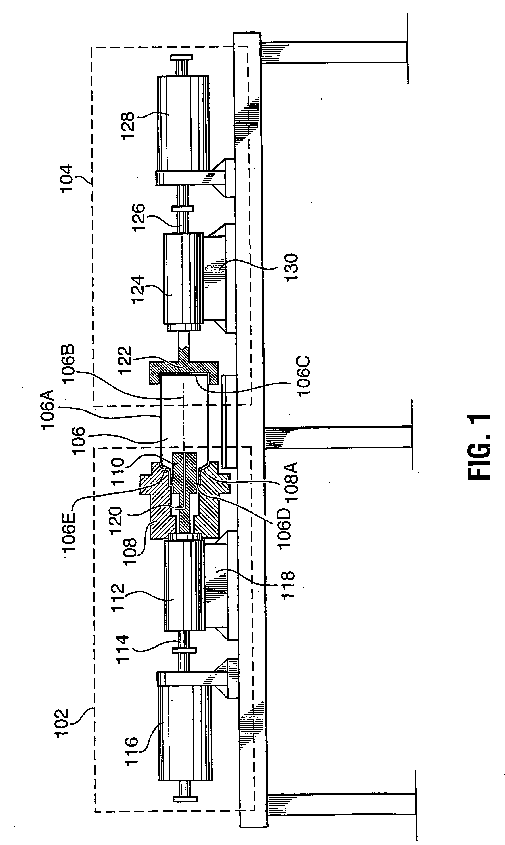
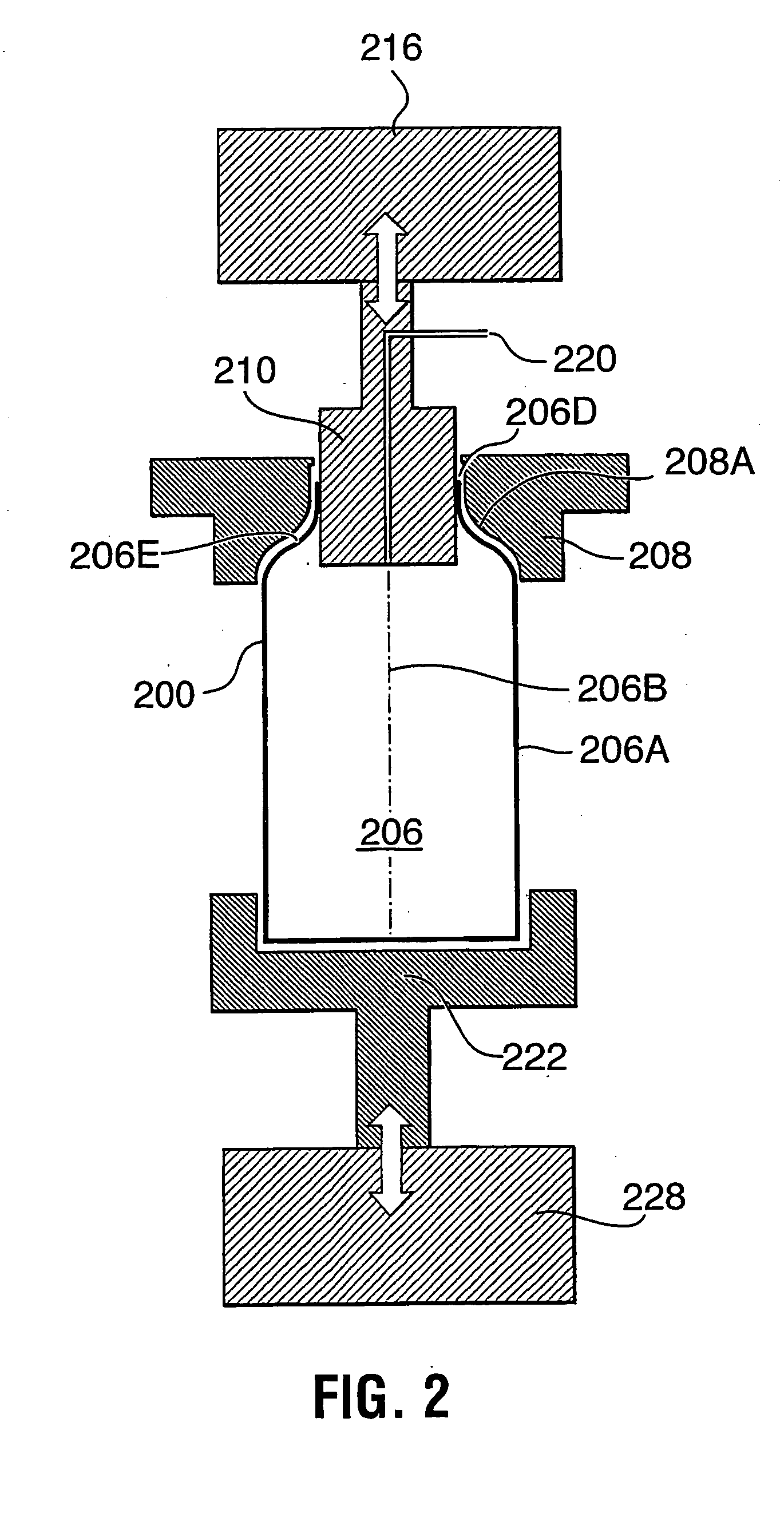
[0014] In a particularly preferred form, the present invention may therefore comprise a method of reducing the diameter of the sidewall at the open end of a seamless unitary metal container body having a sidewall disposed about a longitudinal axis and a unitary endwall at one longitudinal end of the sidewall opposite to the open end comprising: placing the container body with the endwall in communication with a drive segment and the sidewall in communication with a forming segment having a
fixed position forming die of curvilinear configuration in longitudinal cross section and located to form a juncture with the original diameter of the sidewall and progressing with further reduction in diameter toward the open end of the container body; driving a knockout ram with a first
linear drive motor that produces a reciprocal motion in the longitudinal axis relative to the container; drawing a knockout that is connected to the knockout ram, the knockout disposed to engage an interior surface of the open end of the container and having a substantially uniform reduced diameter corresponding to the reduction in diameter at the curvilinear configuration of the forming die; extending the knockout longitudinally with the first
linear motor to a depth within the open end of the container body beyond the juncture with the original diameter of the sidewall; driving a pusher ram with a second
linear drive motor producing a reciprocal motion in the longitudinal axis relative to the container; engaging an exterior surface of the endwall of the container with a pusher pad that is driven by the pusher ram; transmitting a linear force by the second
linear motor through the pusher ram to the pusher pad to the endwall of the metal container to the sidewall of the metal container thus forcing the sidewall into the curvilinear portion of the forming die; retracting the knockout while the linear force is being applied to the metal container during the die forming process; reducing the diameter of the sidewall that is contiguous to the open end of the unitary can body as the container reaches an endpoint of the curvilinear configuration within the forming die.
[0017] The present invention has numerous advantages over prior art. These include a high degree of versatility in forming operations and a capability to change operating parameters
on the fly. Variables such as motion, force and velocity are programmable and highly adjustable at anytime during the forming
stroke. In combination with this variability the present invention allows for alteration of the
programming in real time, and thus, modifications to the
metal forming can be accomplished rapidly and without shutting down or retooling the production equipment. This real time alteration of
metal forming allows the apparatus to be utilized as a development tool to set manufacturing parameters on production machines that do not possess such variability.
[0018] The forming variables and associated ratios can be customized and easily adjusted for individual operations and can be controlled independently for each stage in a multiple stage
machine. This can be accomplished on the “push” side of the forming operation and also on the “pull side” with the same or different forces. These additional motions can be used for multiple necking stages or any other operation that require
linear motion such as expandable mandrels or for performance of other operations (i.e., bottom piercing etc.).

