LSI package provided with interface module

a technology of interface module and package, applied in the field of lsi package, can solve the problems of increasing the number of interposers, increasing the difficulty of mounting an interposer on a board in the actual mounting process of the interposer, and further reducing the operation speed

Inactive Publication Date: 2005-07-21
KK TOSHIBA
View PDF3 Cites 31 Cited by
  • Summary
  • Abstract
  • Description
  • Claims
  • Application Information

AI Technical Summary

Benefits of technology

[0010] In view of these situations, it is an object of the present invention to provide an LSI package provided with an I / F module which can be manufactured through the existing production line and is not accompanied by extremely complicated configuration, and to provide an interposer and an I / F module which are used in the LSI package, a signal processing LSI mounted on the interposer so as to implement the LSI package, a monitoring circuit of the LSI package configured to monitor electrical connection between the signal processing LSI and the I / F module.

Problems solved by technology

However, the operation speed on a board level, or a printed circuit board mounting the signal processing LSI, is still lower than the operation speed in the signal processing LSI, although the operation speed in the signal processing LSI is inherently high, and further, on a rack level packaging hierarchy implemented by the printed circuit boards, the operation speed becomes further lower.
The above-mentioned operation speed problems are caused by increases in transmission loss, noise, and electromagnetic interference associated with the electrical interconnections, which increase more and more as the operation frequency becomes higher.
Therefore, such a tendency the packaging technology limits the operation speed of the system rather than the operation speed of the signal processing LSI, has become more and more significant recently in the electrically interconnected device.
In the above-mentioned earlier technology, it is difficult to mount an interposer on a board in an actual interposer mounting process, since the mounting of the interposer on the board is carried out in a condition where the interposer is mingled with the I / F module.
For instance, since the I / F module has an optical transmission line such as an optical fiber, etc, it is not possible to give heat treatment by putting the optical fiber into a solder reflow furnace of the interposer as it is.
The problem is not limited to a case in which the optical transmission line is employed, since the same problem arises when an electrical transmission line such as a small coaxial cable is used for the transmission line.
However, in the detachable optical connector methodology, protectors for protecting optical semiconductor elements and optical connectors from mechanical damage and pollution are required.
Because of these requirements, there was a problem being that the mounting condition of other parts which are supposed to be mounted on the same board does not meet with the mounting condition of the I / F module and that existing board assembly equipment are not able to be applied to as they are.
Furthermore, the configuration becomes more and more complicated because pressure mechanism and holding mechanism of the optical connector must be provided in the detachable optical connector methodology, and the manufacturing cost drastically increases.

Method used


Image

  • LSI package provided with interface module
  • LSI package provided with interface module
  • LSI package provided with interface module

Examples


first embodiment

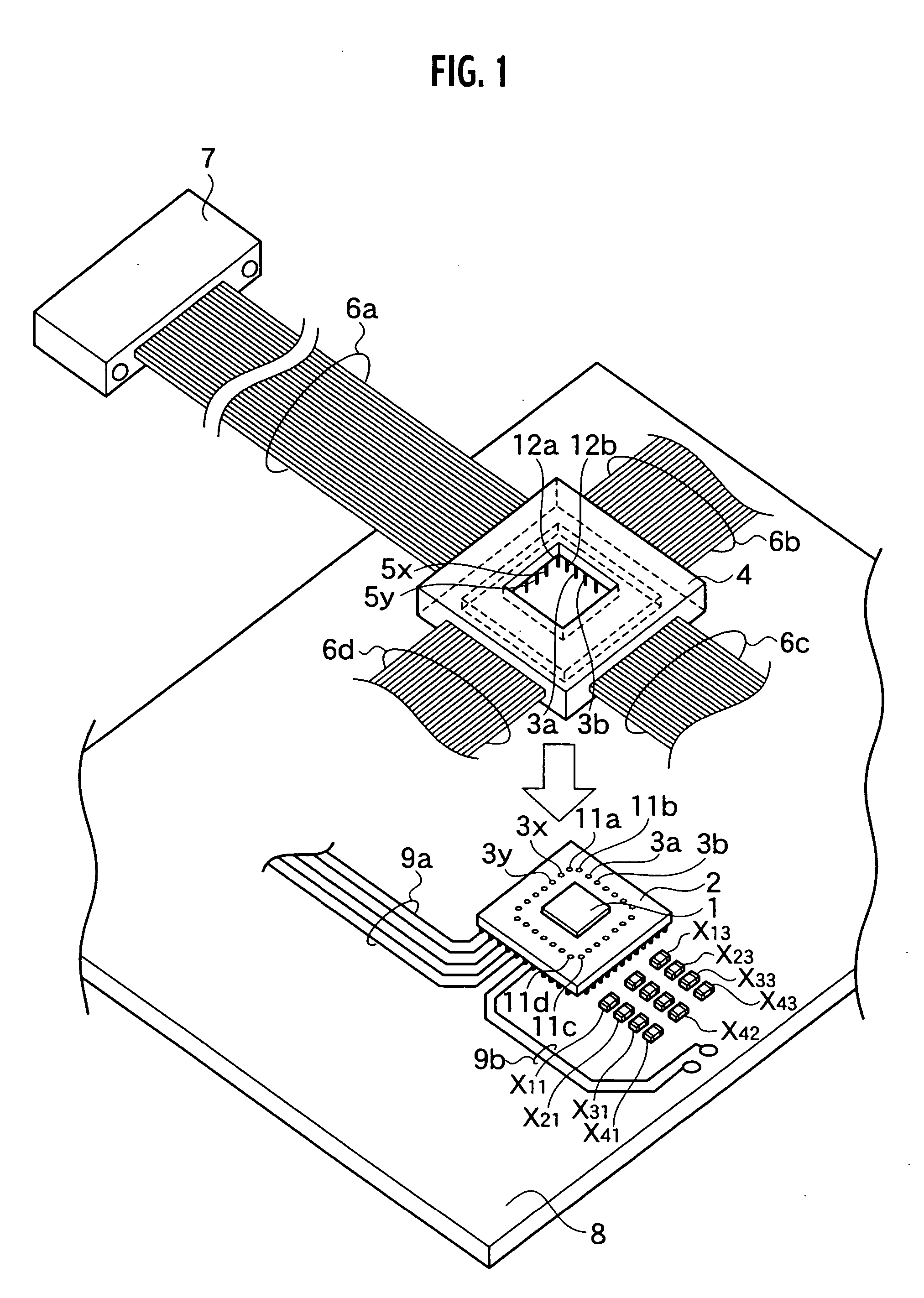
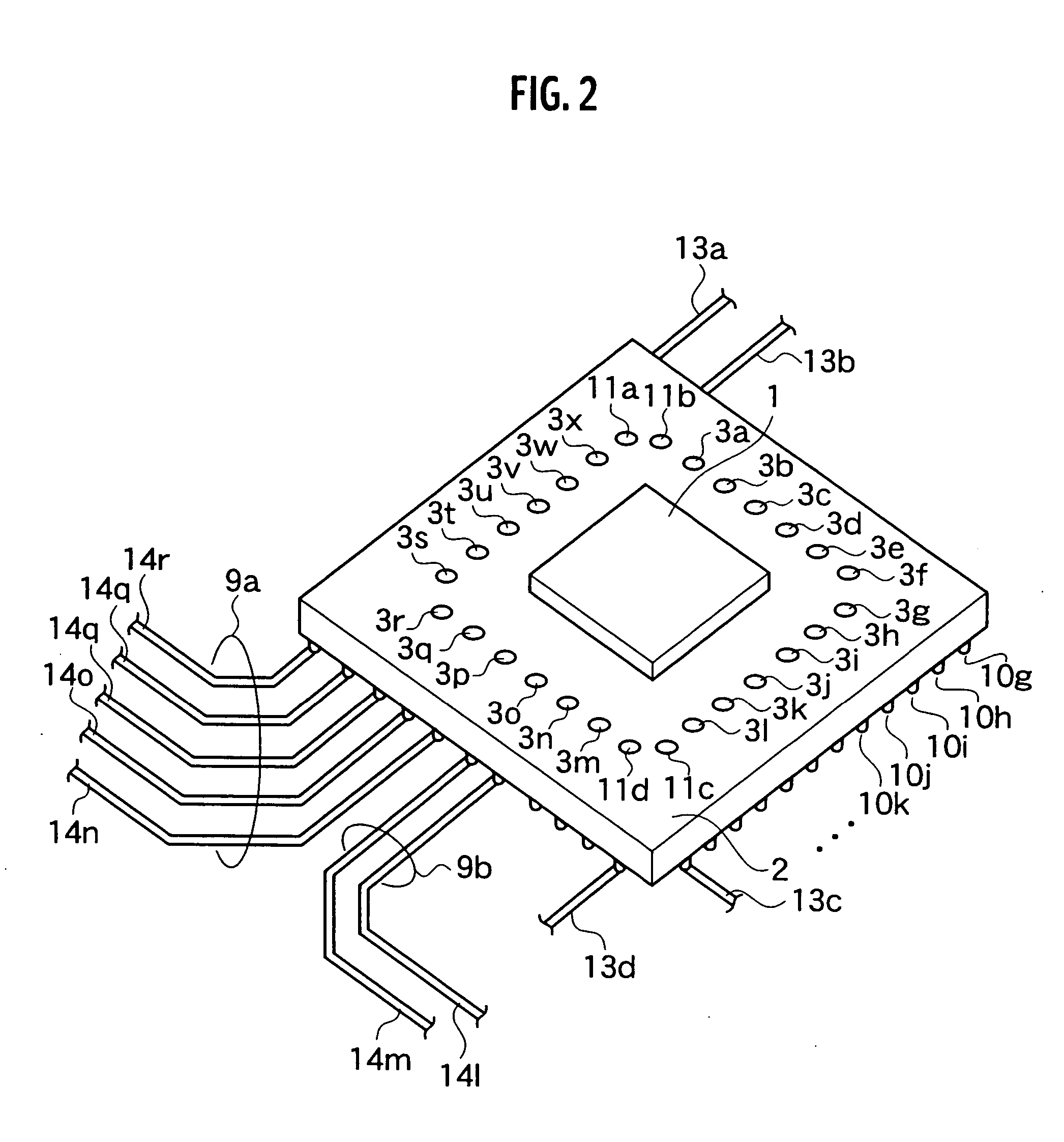
[0042] As shown in FIG. 1, an LSI package according to a first embodiment of the present invention includes an interposer 2, a signal processing LSI 1, which is mounted on the interposer 2 and an I / F module 4, which is electrically connected with an interposer 2. The interposer 2 is employed to facilitate electrical connection between the signal processing LSI 1 and the printed wiring board 8 such that the interposer 2 can be connected to the printed wiring board 8 by electric joints. When the signal processing LSI 1 is taken as the zero-th packaging hierarchy level, “a first level package” is implemented by the signal processing LSI 1 and the interposer. And by mounting the I / F module 4 on “the first level package”, the LSI package as “a second level package” is completed. In addition, “a third level package” is implemented by a combination of “the second level package” and the printed wiring board 8. The solder balls are shown in FIG. 2 as “board-connecting joints 10a, 10b, . . . ...

second embodiment

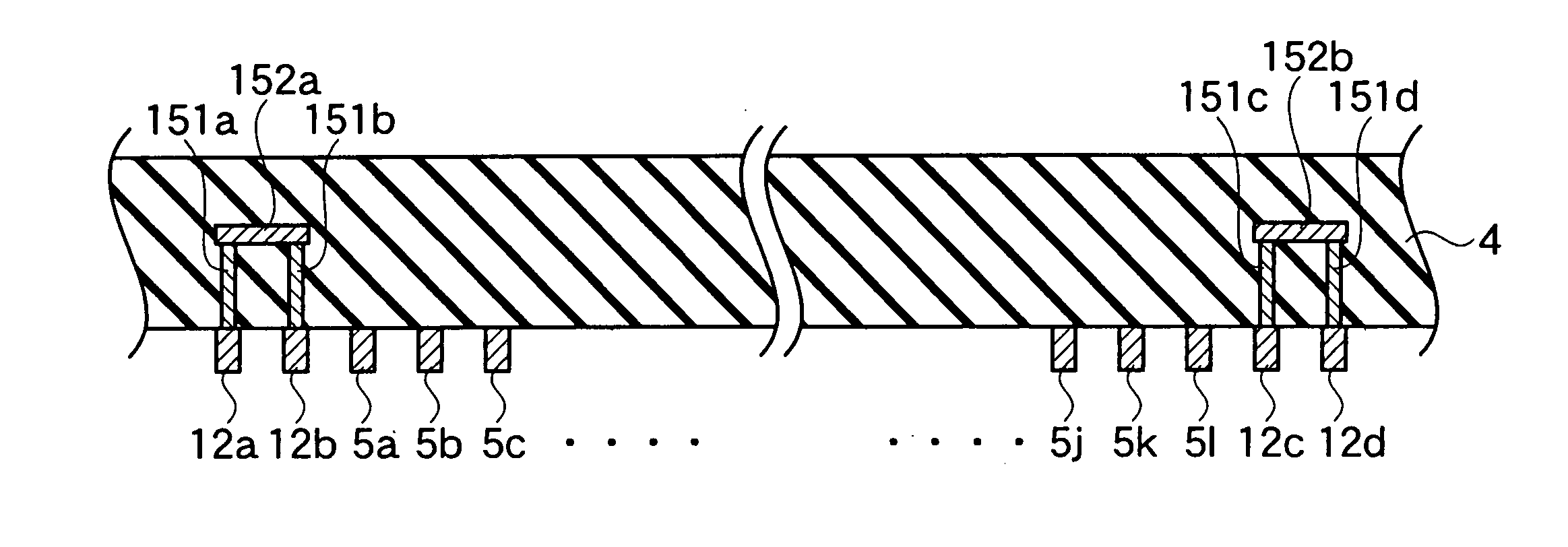
[0069] In the LSI package according to the first embodiment of the present invention, the module-site electric joints (second electric joints) 5a-5x and the module-site monitoring terminals (second monitoring terminals) 12a, 12b, 12c and 12d are implemented by micro pins, and the interposer-site electric joints (first electric joints) 3a-3x and the interposer-site monitoring terminals (first monitoring terminals) 11a, 11b, 11c and 11d are implemented by micro sockets, as shown in FIG. 6 and FIG. 7, joints having a more simpler configuration such as where opposing upper and lower metallic film patterns (lands) join with each other may well be adopted as the electric joints and the monitoring terminals of the monitoring circuit in a second embodiment.

[0070]FIG. 6 shows the enlarged bird's-eye view of an interposer 2 and the configuration around the interposer 2 according to the second embodiment of the present invention. The interposer 2 is connected to board wirings 14l, 14m, 14n, ....

third embodiment

MODIFICATION OF THIRD EMBODIMENT

[0093] A similar monitoring circuit can be established by a configuration spanning three columns of the electric joints in the double concentric rectangular ring as shown in FIGS. 10A and 10B. In FIG. 10A, the interposer-site electric joints (first electric joints) 3xo and 3xi at the third column are used for the additional monitoring terminals. An additional conductive path (short-circuit path) 17 is formed between the interposer-site electric joint 3xi at the third column and the interposer-site monitoring terminal (first monitoring terminal) 11d at the second column. The additional conductive path (short-circuit path) 17 faces a row in which the third conductive path (short-circuit path) 16 between the first and second columns is formed so as to implement a zigzag configuration with the conductive path (short-circuit path) 16. Although the feature that a monitor wiring 13a is connected to an interposer-site electric joint 11c of the first column is...


PUM


Abstract

A LSI package encompasses: an interposer having board-connecting joints, which facilitate connection with a printed wiring board, and module-connecting terminals, part of the module-connecting terminals are assigned as interposer-site monitoring terminals; a signal processing LSI mounted on the interposer; and an I / F module having a plurality of interposer-connecting terminals, which are arranged to correspond to arrangement of the module-connecting terminals, and a transmission line to establish an external interconnection of signal, which is transmitted from the signal processing LSI, part of the interposer-connecting terminals are assigned as module-site monitoring terminals. The interposer-site and module-site monitoring terminals are configured to flow a monitoring current to confirm electric contact between the signal processing LSI and the I / F module.

Description

CROSS REFERENCE TO RELATED APPLICATIONS AND INCORPORATED BY REFERENCE [0001] This application claims benefit of priority under 35 USC 119 based on Japanese Patent Application No. P2003-435836 filed Dec. 26, 2003, the entire contents of which are incorporated by reference herein. BACKGROUND OF THE INVENTION [0002] 1. Field of the Invention [0003] The present invention relates to an LSI package provided with an interface (I / F) module, an interposer and an I / F module which are used in the LSI package, a signal processing LSI mounted on the interposer so as to implement the LSI package, a monitoring circuit of the LSI package configured to monitor an electrical connection between the signal processing LSI and the I / F module. [0004] 2. Description of the Related Art [0005] With improvements in performance of semiconductor active elements such as bipolar transistors and field-effect transistors, the remarkable developments of operation speed is attempted in large scale integrated circuits...

Claims


Application Information

Patent Timeline
Patent Type & Authority Applications(United States)
IPC IPC(8): H01L23/12G02B6/42H01L23/48H01L23/498H01L23/50H01L23/52H01L25/10H01L25/16H01L31/0232H05K1/02H05K1/14H05K7/02
CPCH01L23/49827H01L2924/09701H01L2924/15311H01L2924/3011H05K1/0268H05K1/141H05K7/023H01L2924/0002H05K2201/049H05K2201/10704H05K2201/10719H01L25/18H01L2924/00H01L23/498H01L23/52H01L23/50
Inventor FURUYAMA, HIDETOHAMASAKI, HIROSHI
Owner KK TOSHIBA
Why Eureka
Try Eureka