Multi-channel display driver circuit incorporating modified D/A converters
a driver circuit and display screen technology, applied in the direction of digital-analog converters, instruments, computing, etc., can solve the problems of overshoot distortion of dc level, more serious harmonic distortion and flickering, and achieve the effect of reducing the chance of simultaneous switching of digital comparators, reducing the effect of first harmonics and flickering on the display screen, and simple architectur
- Summary
- Abstract
- Description
- Claims
- Application Information
AI Technical Summary
Benefits of technology
Problems solved by technology
Method used
Image
Examples
third embodiment
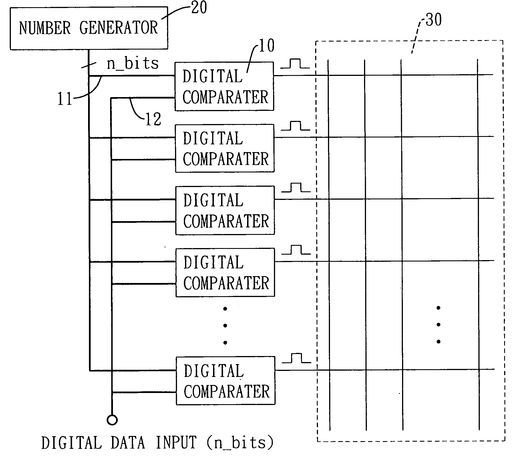
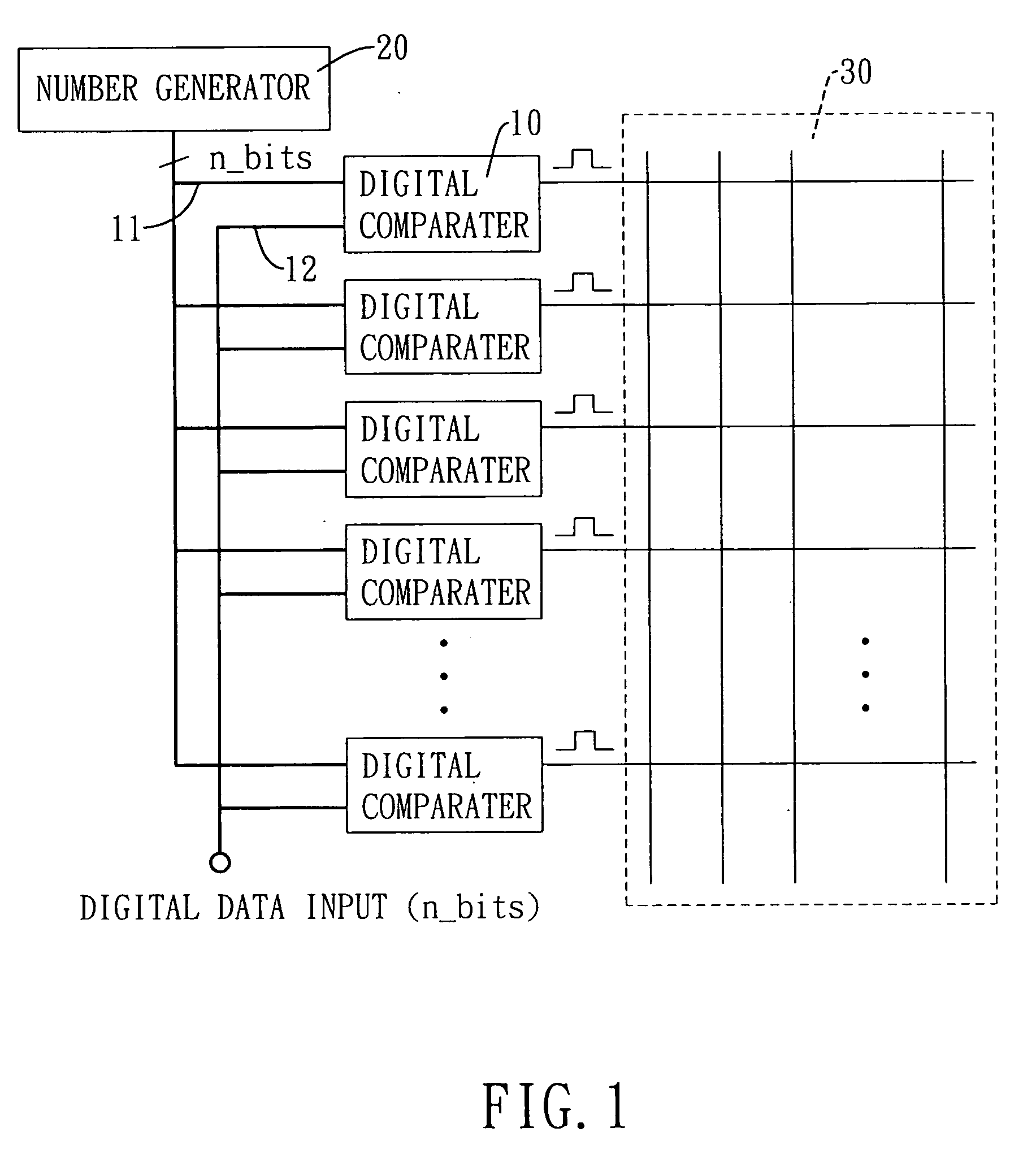
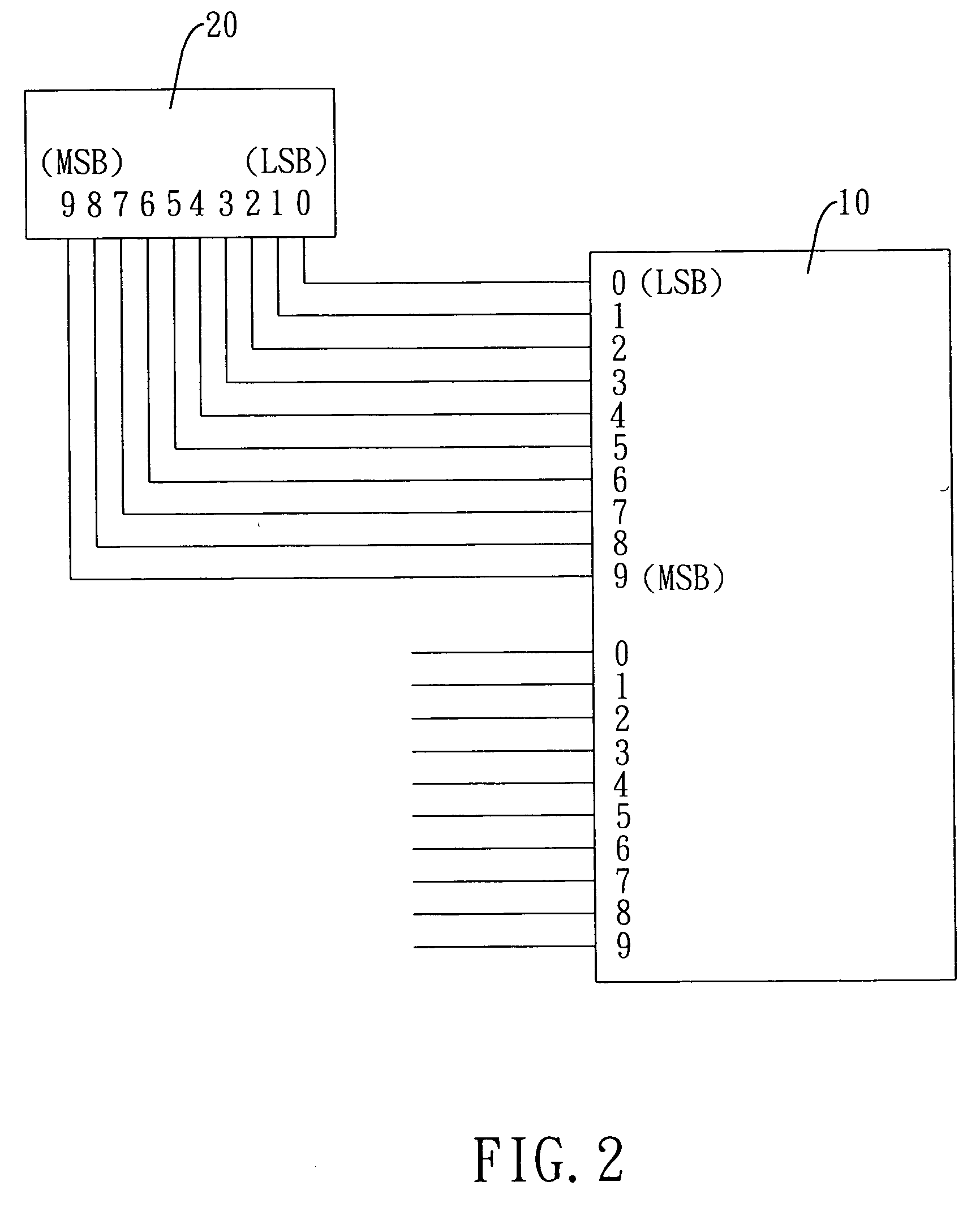
[0063] With reference to FIG. 4A, a third embodiment in accordance with the present invention is designed to correct the output DC level distortion of a conventional PWM D / A converter circuit. The number generator (20) is implemented by a sequential counter (20′) with multiple output bits. The output bits of the sequential counter (20′) are non-sequentially connected to the bit lines of the reference input (11) of each digital comparator (10). For example, the lowest bit (LSB) of the sequential counter (20′) is not correspondingly connected to the lowest bits (LSB) of all the digital comparators (10). Therefore, each digital comparator (10) is provided with an individual non-sequential reference signal derived from the sequence value.
[0064] Still referring to FIG. 4A, although each digital comparator (10) is provided with the non-sequential reference signal, it is noted that all digital comparators (10) still receive the same non-sequence reference signal at any given time from the ...
fourth embodiment
[0065] Therefore, to overcome the above problem, in the fourth embodiment, as shown in FIG. 4B, the connection order between the output of the sequential counter (20′) and the reference input of each digital comparator (10) is independently altered, whereby all digital comparators (10), will not receive the same non-sequence value. Therefore the chance of simultaneous switching of digital comparators (10) and electromagnetic interference will be considerably reduced.
[0066]FIG. 5 shows the pseudo-random logic circuit to form the required random number generator for one of the preferred embodiments. According to the present invention, the 10-bit number generator is implemented by ten D-type flip-flops. The pseudo-random logic circuit for the above random number generation can be expressed in the Verilog™ logic programming language (for example, using a 10-bit random number generator):
module RandGen (reset, clk, randpat);input reset;*defining reset terminal (reset) as an inputinput c...
PUM
 Abstract
Description
Claims
Application Information
 - R&D
- Intellectual Property
- Life Sciences
- Materials
- Tech Scout
- Unparalleled Data Quality
- Higher Quality Content
- 60% Fewer Hallucinations
Browse by: Latest US Patents, China's latest patents, Technical Efficacy Thesaurus, Application Domain, Technology Topic, Popular Technical Reports.
© 2025 PatSnap. All rights reserved.Legal|Privacy policy|Modern Slavery Act Transparency Statement|Sitemap|About US| Contact US: help@patsnap.com


