Weight-compensating device

a compensating device and weight technology, applied in the direction of boring/drilling components, manufacturing tools, metal-working machine components, etc., can solve the problems of inability to move accelerations of more, the total mass which is increased on the whole entails serious problems with respect to the inertia of the component, and the increase in the mass of the whole entails serious problems, so as to achieve good thermal properties, limit the precision of movement, and the effect of hardly heating

Active Publication Date: 2005-07-21
P&L GMBH & CO KG
View PDF6 Cites 16 Cited by
  • Summary
  • Abstract
  • Description
  • Claims
  • Application Information

AI Technical Summary

Benefits of technology

[0021] A further essential advantage of the invention follows from the good thermal characteristics. Hence, the weight compensating device of the invention does not lead to an undesired heating up of specific parts of the total system, which in turn could limit the precision of the movement. Since only very small air masses are moved between the negative pressure body and the accumulator, the air is hardly heated up even in the case of a long-lasting, rapid and reversing movement of the component. The low friction of the negative pressure body (vacuum hose) is also instrumental in virtually preventing any heating up of the negative pressure volume, also in the case of very high loads.
[0022] These and other details, features and advantages of the present invention will become apparent to those skilled in the art from the following detailed description, which, taken in conjunction with the annexed drawings, discloses a preferred embodiment of the present invention.

Problems solved by technology

The already known solutions are marked by the drawback that the sum of the masses to be moved will be increased considerably when a counterweight is used because the mass of the weight compensating device has to be added to the mass of the component.
The total mass which is increased on the whole entails serious problems with respect to the inertia of the component.
For instance, it is not possible to move accelerations of more than 1 g because this will otherwise damage the weight compensating device or impair its functional reliability.
In particular, cables or the like, used by the weight compensating device, cannot be held under tension for a long period of time.
Further problems are created by accelerations that arise and necessary decelerations.
In hydraulic and pneumatic solutions, additional friction is caused by the use of hydraulic cylinders or pneumatic cylinders during movement of the component.
Additional friction arises on account of the piston seals of such piston / cylinder arrangements.
Hence, the overall problem arises that, upon a directional reversal of the movement of the component, frictional forces have to be overcome that are quite considerable, and that large additional masses have to be accelerated and decelerated, respectively.
Especially in machine tools in which three-dimensional operating movements are to be created, this results in undesired flaws, e.g. so-called quadrant jumps in circles.
Further drawbacks arise with respect to the linear drives used in modern machine tools.

Method used


Image

  • Weight-compensating device
  • Weight-compensating device

Examples


Embodiment Construction

[0025] A selected embodiment of the present invention will now be explained with reference to the drawings. It will be apparent to those skilled in the art from this disclosure that the following description of the embodiment of the present invention is provided for illustration only and not for the purpose of limiting the invention as defined by the appended claims and their equivalents.

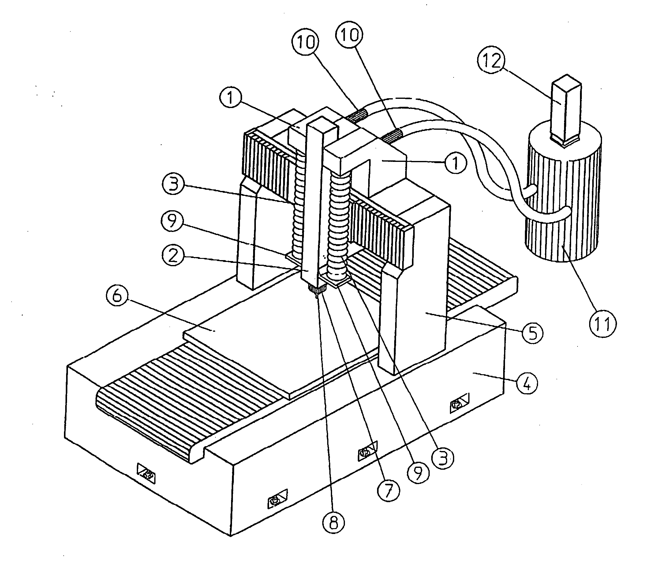
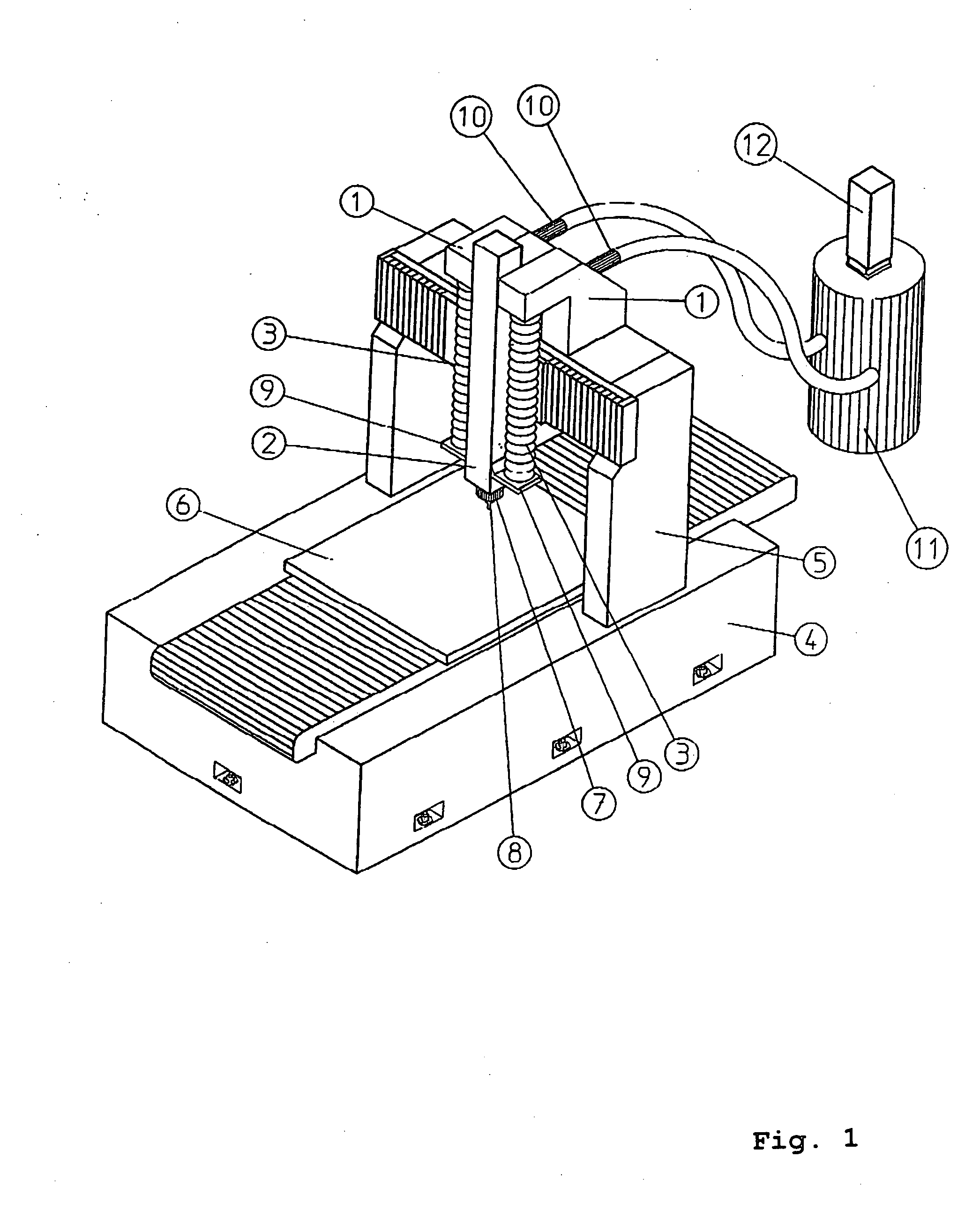
[0026]FIG. 1 is a schematic perspective illustration showing a machine tool with a machine bed 4 on which a portal 5 is supported. The machine bed 4 has movably arranged thereon a table 6 which can carry a workpiece (not shown).

[0027] The portal 5 supports a carrier 1 which is laterally displaceable. The carrier 1, in turn, supports thereon a vertically movable component 2 which forms an axial unit with a spindle 7 and a tool 8. The respective drives are not shown in detail for the sake of a clear illustration. It follows from the resulting movement paths that the tool 8 is movable in at least thr...


PUM

PropertyMeasurementUnit
pressureaaaaaaaaaa
lengthaaaaaaaaaa
negative pressureaaaaaaaaaa

Abstract

The present invention relates to a weight compensating device comprising a carrier and a component which is supported on the carrier and is displaceable particularly in vertical direction by means of a drive, characterized in that the carrier and the component have arranged thereinbetween at least one negative pressure body of a variable length which is connected to a negative pressure source for compensating the weight acting on the component.

Description

BACKGROUND OF THE INVENTION [0001] 1. Field of the Invention [0002] The present invention relates to a weight compensating device comprising a carrier and a component which is supported on the carrier and is displaceable particularly in a vertical direction by means of a drive. [0003] 1. Background Information [0004] Especially in the field of machine tools, components which are in part relatively heavy must be displaced and / or precisely held in vertical direction against their weight or against gravity. [0005] Many mechanisms are already known wherein a weight compensating device is used for compensating at least part of the weight / gravity of the component and for relieving the drive at the same time. The solutions include, for instance, counterweights, which are e.g. held via a deflection pulley and a rope, or the like. Further mechanisms show hydraulic or pneumatic solutions. [0006] The already known solutions are marked by the drawback that the sum of the masses to be moved will...

Claims


Application Information

Patent Timeline
Patent Type & Authority Applications(United States)
IPC IPC(8): B23Q11/00
CPCB23Q11/001Y10T409/309688Y10T408/92Y10T409/307728Y10T409/308288
Inventor RODERS, JURGEN
Owner P&L GMBH & CO KG
Why Eureka
Try Eureka