Formation water treating system and formation water treating method, and power generator

a technology of formation water and water treatment system, which is applied in the direction of electrochemical generators, cell components, cell components, etc., can solve the problems of reducing power generation efficiency, affecting the efficiency of power generation, and affecting the placement of devices, so as to avoid interference of flow, prevent the oxidizer supply groove from being blocked, and stabilize the power generation efficiency

Active Publication Date: 2005-07-21
MURATA MFG CO LTD
View PDF7 Cites 34 Cited by
  • Summary
  • Abstract
  • Description
  • Claims
  • Application Information

AI Technical Summary

Benefits of technology

[0061] By disposing the water by the water disposal means provided on at least the midway of the oxidizer supply groove, the power generation apparatus of the present invention is successful in preventing the oxidizer supply groove from being clogged d

Problems solved by technology

It is, however, known that the water produced at the cathode or water back-diffused through the proton conductor film towards the anode side interferes flow of the supplied source material such as hydrogen gas, or stagnates in air feed grooves for feeding oxygen (air), and this is causative of lowering in the power generation efficiency.
The fuel cell based on the technique of discharging the water in its liquid form with the aid of gravity is, however, not applicable to small-sized devices such as portable electronic devices, because placement of the device is limited.
On the other hand, the technique of blowing the water in its liquid form is not practical because it is realizable only by using a large-sized pump.
The aforementioned technique described in Patent Document 1, however, suffers from a problem in that the water cannot completely be discharged from the diffusion layer to the external, and the water stayed in the internal becomes water droplets to thereby interfere the gas supply to the catalyst layer.
The technique also raises a problem in that the water interferes flow of the source materials also on the anode side, because the amount of water back-diffused through the proton conductor film towards the anode side increases unless otherwise the water generated on the cathode side is successfully discharged to the external.
The water in problem may be discharged as being carried by a gas flow under control of pressure or flow rate of oxygen or air at the cathode, but it is difficult for flat-type or small-sized power generation cells, having a cathode often configured as of open air type, to discharge the water as being carried by the gas flow under control of p

Method used


Image

  • Formation water treating system and formation water treating method, and power generator
  • Formation water treating system and formation water treating method, and power generator
  • Formation water treating system and formation water treating method, and power generator

Examples


first embodiment

[0088] First, the water disposal system exemplified as a first embodiment will be explained.

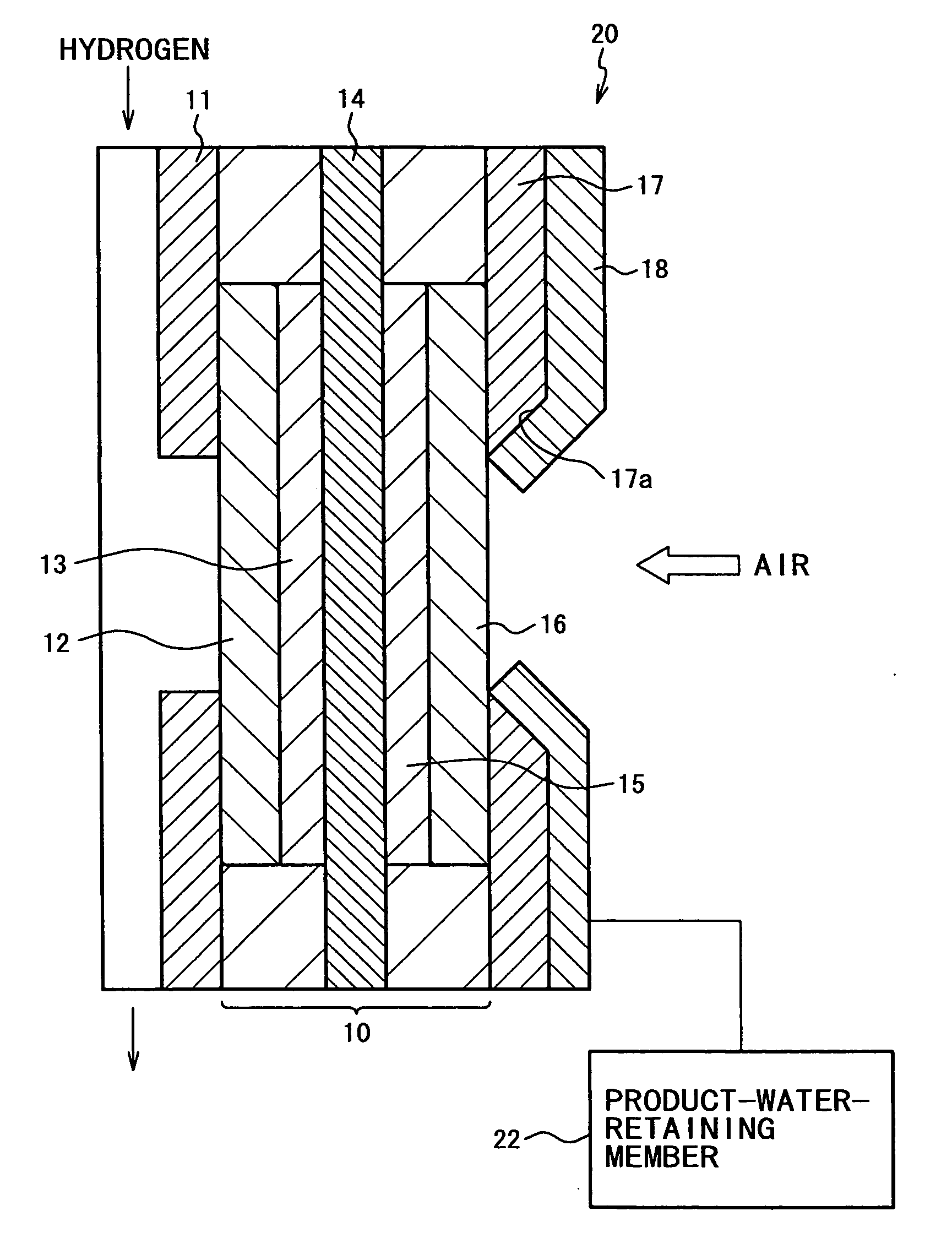
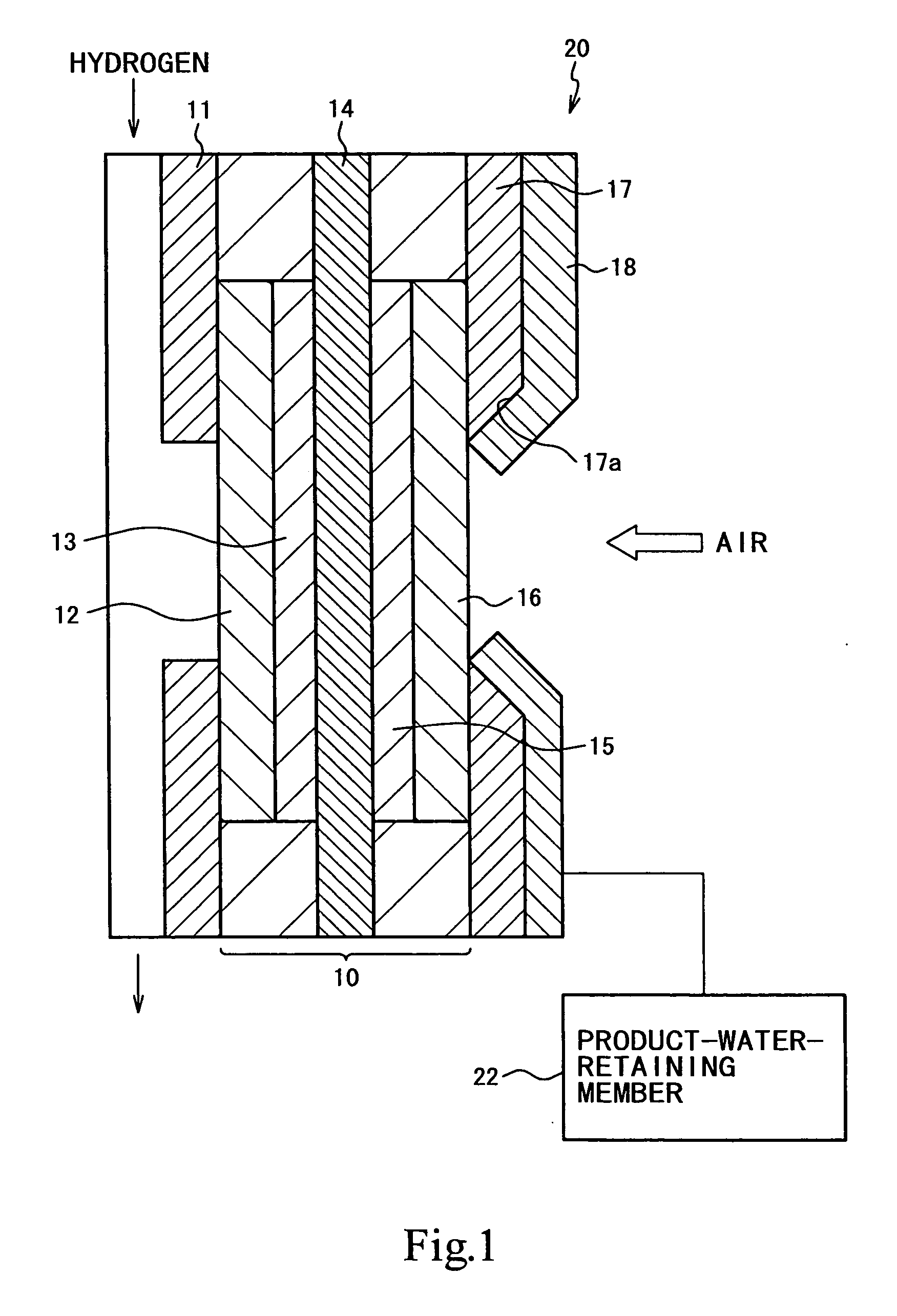
[0089]FIG. 1 is a sectional view showing an exemplary power generation apparatus to which the water disposal system is applied. The water disposal system has a power generator, a water-absorbing member disposed to the power generator as being extended therefrom, for recovering and moving the water with the aid of capillary phenomenon, and a water-retaining member for temporarily accumulating the water.

[0090] More specifically as shown in the figure, a power generation apparatus 20 has, as major constituents, a hydrogen-side current collector 11 provided to an anode which corresponds to a hydrogen-side electrode, an oxygen-side current collector 17 provided to a cathode which corresponds to an oxygen-side electrode, and a power generator 10 held between the hydrogen-side current collector 11 and oxygen-side current collector 17.

[0091] On the oxygen-side current collector 17 of the power gene...

second embodiment

[0129] Next paragraphs will describe a water disposal system exemplified as the

[0130] The second embodiment relates to a fuel cell as a power generation apparatus to which the water disposal system is applied. The fuel cell is configured by stacking a plurality of the power generator, so-called MEA, which has a predetermined electrolyte film provided between an anode and a cathode, wherein the MEA is held between thin-plate-formed separators having, as being formed on the front and back surfaces thereof, a hydrogen supply groove as a fuel supply groove for supplying hydrogen to the anode, and an air supply groove as an oxidizer supply groove for supplying air to the cathode, so as to produce power generation by supplying hydrogen and air through the separators.

[0131] The fuel cell is specifically configured as having a means for disposing the water, provided at least on the midway portion of the air supply groove formed on the separator, to thereby make it possible to efficiently a...

third embodiment

[0201] A water disposal system exemplified as a third embodiment will be explained.

[0202] The third embodiment is a further modification of the above-described first and second embodiments, aiming at further raising efficiencies in water absorption and collection of generated electricity, by providing a water-absorbing layer having at least water absorbency, air permeability and electro-conductivity, between the diffusion layer and the collector which serves as the current collector.

[0203] In the aforementioned first and second embodiments, it was explained, referring to a fuel cell 300 as the power generation apparatus shown in FIG. 18, that the water, produced during the power generation in a hydrogen-side catalyst layer 302 and an oxygen-side catalyst layer 303 placed on both sides of a predetermined electrolyte film 301, moves to a carbon fiber layer 304 which is a diffusion layer composed of a paper-sheet-formed carbon fiber with a water-repellent finish, and the water is then...


PUM


Abstract

Water disposal systems, apparatuses and methods that employ same, and methods for disposing water produced during power generation are provided. A separator of a fuel cell has an air supply groove formed therein for supplying air as an oxidizer gas to a cathode. The separator is also provided with water-absorbing cloths on the midway portion of the air supply groove. More specifically, the water-absorbing cloth is provided on the separator (110), as a water absorbing member for absorbing the water, so as to cover at least a part of the surface on which the air supply grooves is formed and the water-absorbing clothes is provided along the sidewall of the air supply grooves. Water generated during power generation by the power generator of the present invention is disposed in efficient and reliable manners, under a simple configuration.

Description

CROSS REFERENCES TO RELATED APPLICATIONS [0001] The present application claims priority to Japanese Patent Document Nos. P2002-117319 filed on Apr. 19, 2002, P2002-360491 filed on Dec. 12, 2002; and P2003-073414 filed on Mar. 18, 2003 the disclosures of which are herein incorporated by reference. BACKGROUND OF THE INVENTION [0002] The present invention relates to a water disposal system and a method of disposing water for disposing water produced during power generation by a power generator, and a power generation apparatus using the water disposal system and the method of disposing water, for disposing water produced during power generation. [0003] Fuel cell is a device which supplies a fuel gas, such as hydrogen, together with oxygen (air), and allows the fuel gas and oxygen to electrochemically react with each other to thereby generate electric power on a power generator. The fuel cell is much hopeful for applications to electric cars or hybrid vehicles, in a form of being mounte...

Claims


Application Information

Patent Timeline
IPC IPC(8): H01M8/04H01M8/10H01M8/06
CPCH01M8/04156H01M8/04171Y02B90/18H01M2250/30Y02E60/50H01M8/04291Y02B90/10
Inventor MINEHISA, IMAZATOYAMAURA, KIYOSHIHOKARI, TORU
Owner MURATA MFG CO LTD
Why Eureka
Try Eureka