Semiconductor integrated circuit having multi-level interconnection, CAD method and CAD tool for designing the semiconductor integrated circuit

a technology of integrated circuits and semiconductors, applied in logic circuit coupling/interface arrangements, pulse techniques, instruments, etc., can solve the problems of high current dissipation in power supply wiring, difficult addition of such supplemental power supply wiring, and inevitable redesign of layou

Inactive Publication Date: 2005-07-21
KK TOSHIBA
View PDF8 Cites 30 Cited by
  • Summary
  • Abstract
  • Description
  • Claims
  • Application Information

AI Technical Summary

Benefits of technology

[0018] An aspect of the present invention inheres in a computer-aided design method of multilevel interconnection including first- and second-potential-level power supply wirings for supplying power to a plurality of logic elements in an integrated circuit. That is, the method encompasses: calculating current dissipation consumed by the logic elements, in a ladder network comprising a plurality of current paths flowing through each of the logic elements, the current paths are connected in parallel between a subject first-potential-level power supply wiring and a subject second-potential-level power supply wiring; analyzing a tolerable electro-migration current of the subject first-potential-level power supply wiring; analyzing an interval voltage drop between a control point and a specific position on the subject first-potential-level power supply wiring; and comparing a summation of through-currents flowing the logic elements, which are arranged in a region from the control point to the specific point, with the tolerable electro-migration current, and further comparing the interval voltage drop with a tolerable voltage drop so as to determine an optimum location of a via configured to supply power from the subject first-potential-level power supply wiring to the logic elements.
[0019] Another aspect of the present invention inheres in a designing tool of an integrated circuit having a multilevel interconnection including first- and second-potential-level power supply wirings for supplying power to a plurality of logic elements, encompassing: a current dissipation calculation module configured to calculate current dissipation consumed by the logic elements, in a ladder network comprising a plurality of current paths flowing through each of the logic elements, the current paths are connected in parallel between a subject first-potential-level power supply wiring and a subject second-potential-level power supply wiring; an electro-migration analysis module configured to analyze a tolerable electro-migration current of the subject first-potential-level power supply wiring; a voltage drop analysis module configured to analyze an interval voltage drop between a control point and a specific position on the subject first-potential-level power supply wiring; and a via allocation calculation module 135 configured to compare a summation of through-currents flowing the logic elements, which are arranged in a region from the control point to the specific point, with the tolerable electro-migration current, and further compare the interval voltage drop with a tolerable voltage drop so as to calculate an optimum location of a via configured to supply power from the subject first-potential-level power supply wiring to the logic elements.
[0020] Still another aspect of the present invention inheres in an integrated circuit, encompassing: a plurality of logic elements merged in a semiconductor chip; an interlevel insulator disposed above the logic elements; a subject first-potential-level power supply wiring extending along a fixed direction in a subject wiring level disposed above the interlevel insulator, configured to supply power to the logic elements; a subject second-potential-level power supply wiring in second subject wiring level disposed above the interlevel insulator, being paired with and running in parallel with the subject first-potential-level power supply wiring; and a via allocated in a specific position on the subject first-potential-level power supply wiring, configured to supply the power from the subject first-potential-level power supply wiring to the logic elements, the specific position is determined such that a summation of through-currents flowing the logic elements, which are arranged in a region from a control point to the specific point is smaller than a tolerable electro-migration current, and that an interval voltage drop of the subject first-potential-level power supply wiring from the control point to the specific point is smaller than a tolerable voltage drop.

Problems solved by technology

However, addition of such supplemental power supply wiring is difficult, because routing process of clock signal wirings and other signal wirings is already finished in a semiconductor integrated circuit of a mesh architecture.
That is to say, a technical problem occurs such that, to some extent, redesign of the layout is inevitable in advanced semiconductor integrated circuits.
However, physical design of a semiconductor integrated circuit implemented by the stacked-via architecture has following new problems:
But, because there is a considerable distance between a central portion of the logic element arrangement region and an I / O cell position for power supply, a resistance component of power supply wirings becomes so large in the central portion of the logic element arrangement region that the current is highly dissipated in the power supply wirings.
Therefore, in the central portion, the power supply quantity is insufficient, and the drop of supply voltage is easily generated.
In the meantime, in a crowded area where logic elements are packed in the logic element arrangement region, since the current dissipation by the logic elements is large, the power supply quantity from the stacked-vias is insufficient, and the drop of supply voltage is easily generated.
Therefore, routing process of the signal wirings is restricted by the excessive stacked-vias and wiring efficiency decreases, disturbing the performance improvement, and the enhancement of high integration of the semiconductor integrated circuit becomes difficult.

Method used


Image

  • Semiconductor integrated circuit having multi-level interconnection, CAD method and CAD tool for designing the semiconductor integrated circuit
  • Semiconductor integrated circuit having multi-level interconnection, CAD method and CAD tool for designing the semiconductor integrated circuit
  • Semiconductor integrated circuit having multi-level interconnection, CAD method and CAD tool for designing the semiconductor integrated circuit

Examples


first embodiment

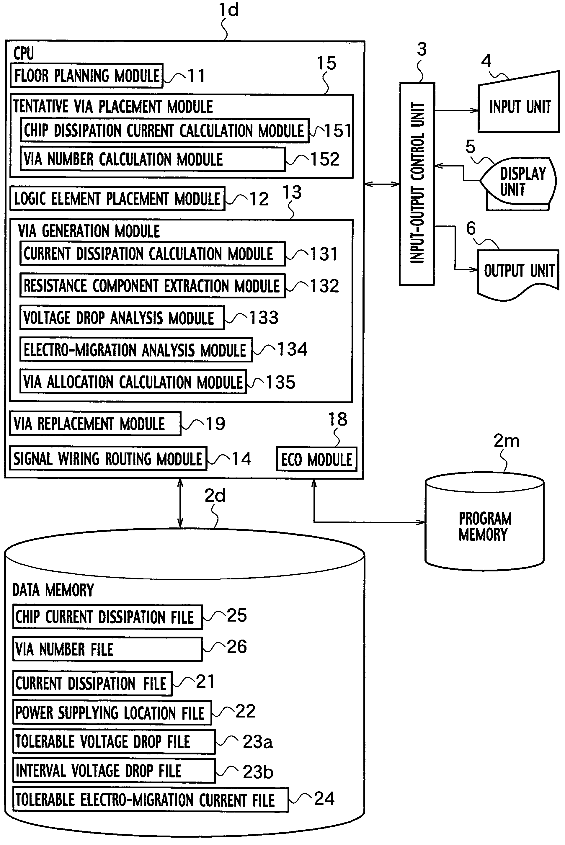
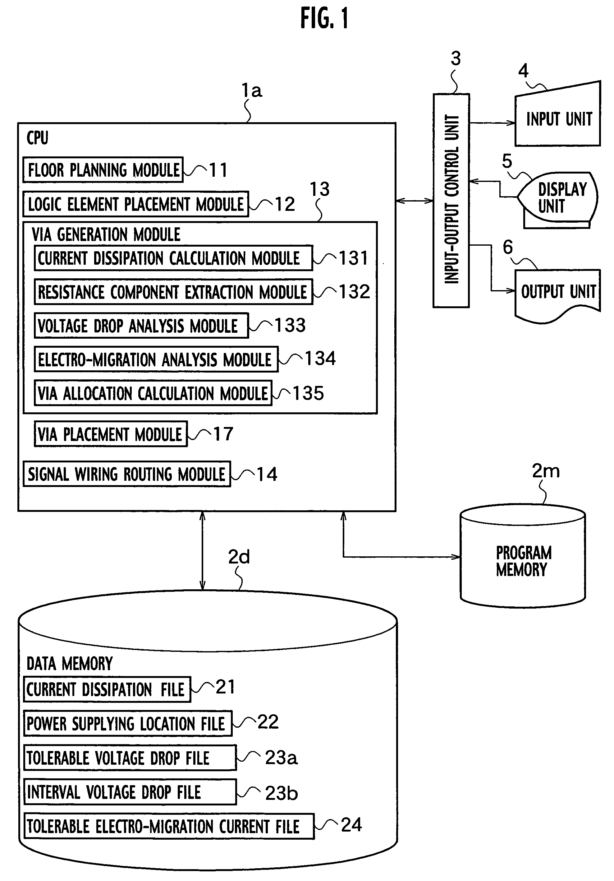
[0049] As shown in FIG. 1, a designing tool according to a first embodiment of the present invention is a computer system encompassing a input unit 4 configured to accept input data and instructions from an operator, a central processing unit (CPU) la configured to control and perform various operations of layout design, etc., an output unit 6 configured to provide layout results, etc., a display unit 5 configured to display input data, intermediate data and output data including the result of layout design, a data memory 2d configured to store various data necessary for layout design of a semiconductor integrated circuit, etc. and a program memory 2m configured to store layout design program of a semiconductor integrated circuit, etc.

[0050] The designing tool of the first embodiment further encompasses an input / output control unit 3. Through the input / output control unit 3, the input unit 4, the output unit 6 and the display unit 5 are connected to the CPU 1a.

[0051] The CPU 1a ha...

second embodiment

[0138] As shown in FIG. 14, a designing tool according to a second embodiment of the present invention is a computer system encompassing an input unit 4 configured to accept input data and instructions from an operator, a CPU 1b configured to control and perform various operations of layout design, etc, an output unit 6 configured to provide layout results, etc. and display unit 5 configured to display input data, intermediate data and output data including the result of layout design a data memory 2d configured to store various data necessary for layout design of a semiconductor integrated circuit, etc. and a program memory 2m configured to store layout design program of a semiconductor integrated circuit, etc.

[0139] The designing tool of the second embodiment further encompasses an input / output control unit 3. Through the input / output control unit 3, the input unit 4, the output unit 6 and the display unit 5 are connected to the CPU 1b.

[0140] The CPU 1b of the designing tool acc...

third embodiment

[0172] As shown in FIG. 19, a designing tool according to a first embodiment of the present invention is a computer system encompassing: an input unit 4 configured to accept input data and instructions from an operator, a CPU 1c configured to control and perform various operations of layout design, etc., an output unit 6 configured to provide layout results, etc., a display unit 5 configured to display input data, intermediate data and output data including the result of layout design, a data memory 2d configured to store various data necessary for layout design of a semiconductor integrated circuit, etc. and a program memory 2m configured to store layout design program of a semiconductor integrated circuit, etc. The designing tool of the first embodiment further encompasses an input / output control unit 3. Through the input / output control unit 3, the input unit 4, the output unit 6 and the display unit 5 are connected to the CPU 1c.

[0173] The CPU 1c provided in the designing tool o...


PUM


Abstract

A computer-aided design method of an integrated circuit includes: calculating current dissipation consumed by logic elements, in a ladder network embracing a plurality of current paths connected between subject first- and second-potential-level power supply wiring; analyzing a tolerable electro-migration current of the subject first-potential-level power supply wiring; analyzing an interval voltage drop between a control point and a specific position on the subject first-potential-level power supply wiring; and comparing a summation of through-currents flowing the logic elements from the control point to the specific point, with the tolerable electro-migration current, and comparing the interval voltage drop with a tolerable voltage drop to determine an optimum location of a via configured to supply power from the subject first-potential-level power supply wiring to the logic elements.

Description

CROSS REFERENCE TO RELATED APPLICATIONS AND INCORPORATION BY REFERENCE [0001] This application claims benefit of priority under 35 USC 119 based on Japanese Patent Application No. P2004-12894 filed Jan. 21, 2004, the entire contents of which are incorporated by reference herein. BACKGROUND OF THE INVENTION [0002] 1. Field of the Invention [0003] The present invention relates to a computer-aided design (CAD) method and a CAD tool executing the CAD method. It is particularly related to the CAD method and the CAD tool of a semiconductor integrated circuit having a multi-level interconnection, with a plurality of logic cells and power supply wirings that supply the logic cells with electric power, and a semiconductor integrated circuit manufactured with mask patterns designed by the CAD method and the CAD tool. [0004] 2. Description of the Related Art [0005] In earlier technology, along each side of a silicon chip, or a single crystal substrate (semiconductor chip) cut into a rectangula...

Claims


Application Information

Patent Timeline
Patent Type & Authority Applications(United States)
IPC IPC(8): G06F17/50H01L21/3205H01L21/82H01L21/822H01L23/52H01L27/04
CPCG06F17/5022G06F17/5077G06F2217/78H01L2924/0002H01L2924/00G06F30/394G06F30/33G06F2119/06G06F30/3308
Inventor ORITA, HIROSHIGE
Owner KK TOSHIBA
Why Eureka
Try Eureka